
When the magic catches on - the KunstZahnWerk competition from CANDULOR always offers a challenge to craftsmanship
Nima Mohammadi
When a flash of magic sparks from one person to another, it is called enthusiasm. As happened at this year's CANDULOR KunstZahnWerk competition. One person had already won, the other, like his colleague and friend, wanted to master this manual challenge as well. And so Nima Mohammadi, dental technician in Lower Bavaria's Breitenberg, decided to request the competition documents from CANDULOR and take part.
On four continents: dedicated full dentures
Together with Nima Mohammadi, 120 participants from four continents registered. CANDULOR received 49 competition entries and documentations from 16 nations by the deadline. Some packages had traveled a long distance to take part in the competition and face the international jury of experts with the proposed solution. Prof. Dr. Frauke Müller, Head of the Gerondontology and Removable Prosthetics Division at the University of Geneva, Switzerland acted as Chairwoman. CDT/DTG Arian Deutsch, owner of Deutsch Dental Arts in Surprise (Arizona) had traveled from the USA for this purpose. In 2011, he took part in the international KunstZahnWerk competition and in 2012 he won the KZW competition North America. Support came from Berlin; MDT Andreas Kunz, owner of Andreas Kunz Zahntechnik and an internationally recognized practitioner and speaker. For CANDULOR, DT Martin Koller, in his role as a total prosthetic technician and trainer with heart and soul, took on the responsible task of evaluating the competition work. Nima Mohammadi could hardly believe becoming one of the top-ranked competitors who immediately won this special total prosthetic award.
Fig. 1: 3rd place in the KunstZahnWerk competition 2019 for Nima Mohammadi (Breitenberg, DE)

Prosthetic Challenge 2019
What was it this time that motivated dental technicians all over the world to prove their skills and say "goodbye" to their spare time for a while? This year's competition was based on the case of a relatively young 42-year-old male patient with very good oral hygiene. Due to an accident, the self-employed person had to wear full dentures. However, they hindered his speech and when chewing. Pressure sores in the lower jaw proved to be an additional hindrance. Repeated new dentures treatment did not lead to any improvement. Therefore, the mandible was provided with four Camlog implants for a partially removable lower hybrid restoration. Patient data including specifications for the horizontal condylar path angle (right: 28 °; left: 30 °), for the esthetic control template with instructions for anterior tooth setup, for the hygiene shape of the lower hybrid denture, for the occlusion concept according to GERBER in tooth-to-tooth occlusion and numerous other factors described the requirements.

That's dental technology: taking up on specifications, implementing them functionally, esthetically and creatively
MODEL ANALYSIS
The model was assembled in an articulator suitable for the total prosthetic concept according to Prof. A. GERBER with a double cone as articulator joint. The double cone enables the simulation of physiological movement patterns in lateral and transversal motion sequences in the form of the natural rotary-sliding movement. The Condylator or the CANDULOR articulator CA 3.0 are suitable for this purpose.
The next step was the model analysis according to LERCH. This is generally only performed on models oriented in the articulator to ensure the correct intraoral relationship in transversal and sagittal direction. The objective of the model analysis is to find out in which areas chewing functional loads are reliably transferred to the denture base without causing the lower denture to tilt or slip (advance forwards) and which occlusion design makes sense for this purpose.
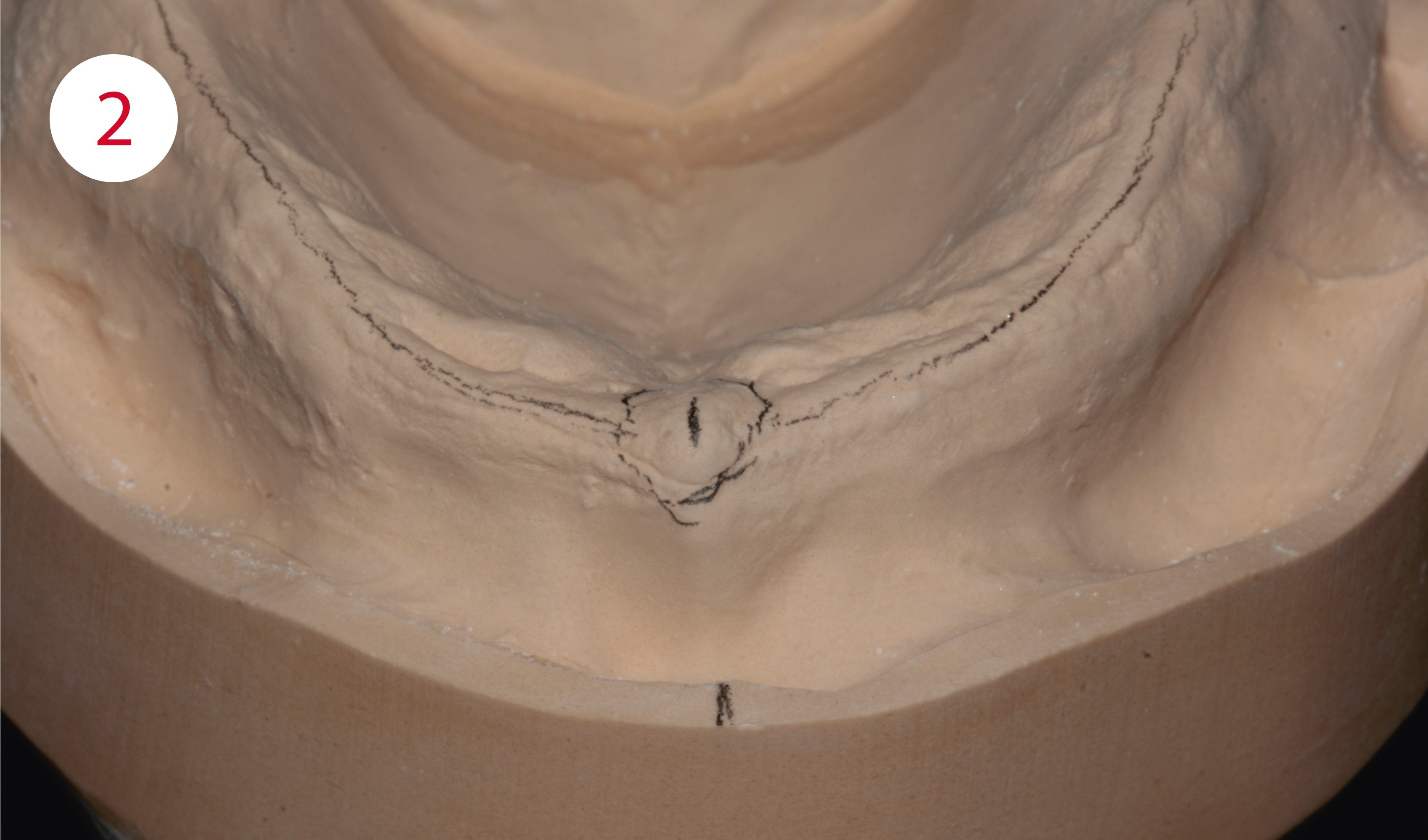
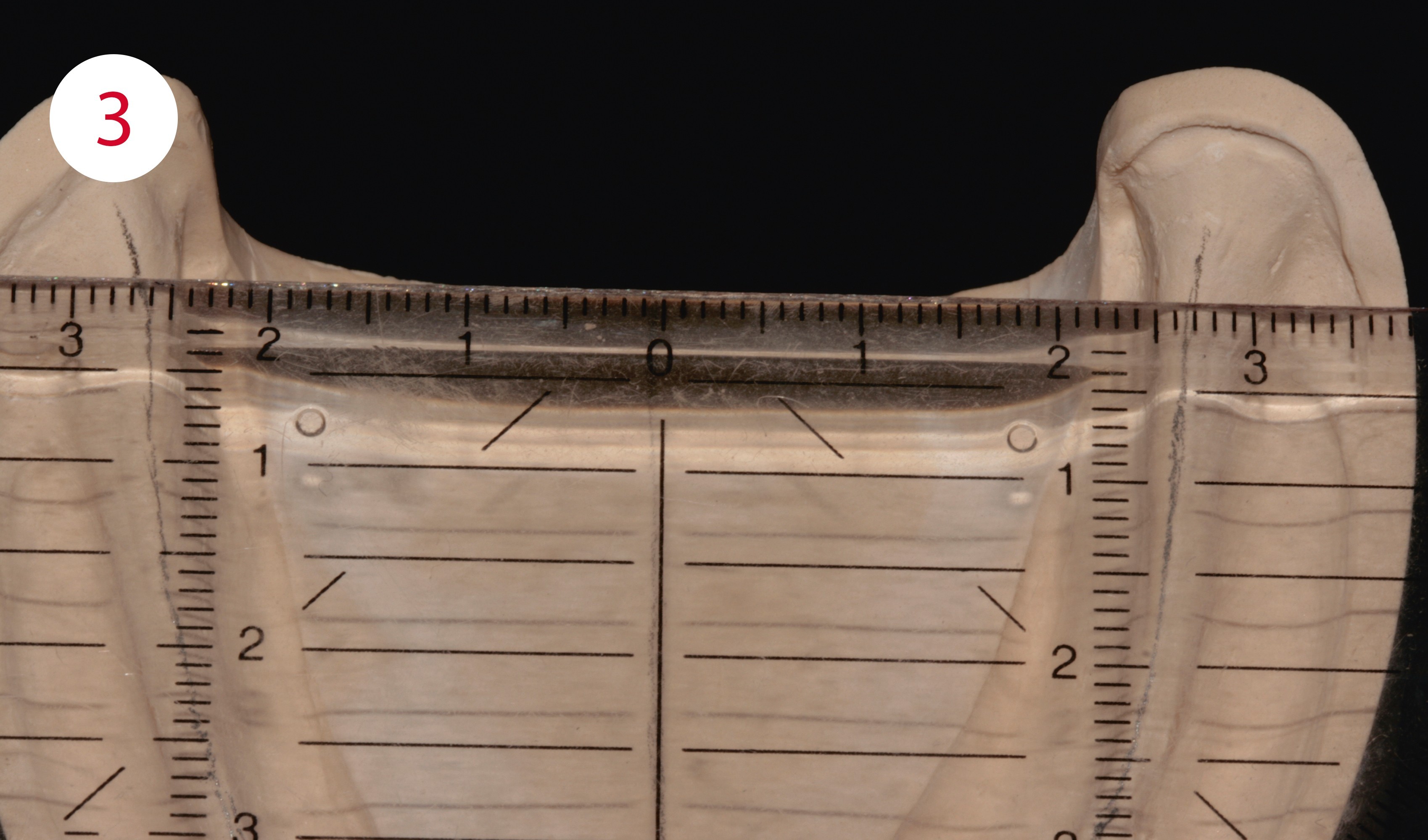
In the maxilla, a secure denture support is created within the area of the deepest points of the vestibular fold. In the mandible the internal limit is the mylohyoid line, and in the external area the oblique line. In the maxilla, the center of the alveolar ridge and the incisive papilla are plotted and the metric model centers determined (Fig. 2). In the mandible, the analysis is somewhat more complex. First determine the metric model center and plot it, then mark the entire course of the alveolar ridge centers to its degree, i.e. plot it. (Figs. 3, 4). The lateral and frontal ridge centers are transferred to the model edges, i.e. extended, so that they can be used as orientation lines for the set-up.
Fig. 2: Model analysis: middle of alveolar ridge and center of incisive papilla (in the mandible: tongue frenulum)
Fig. 3: Model analysis: metric model center here on the mandible
Fig. 4: The lower metric model center
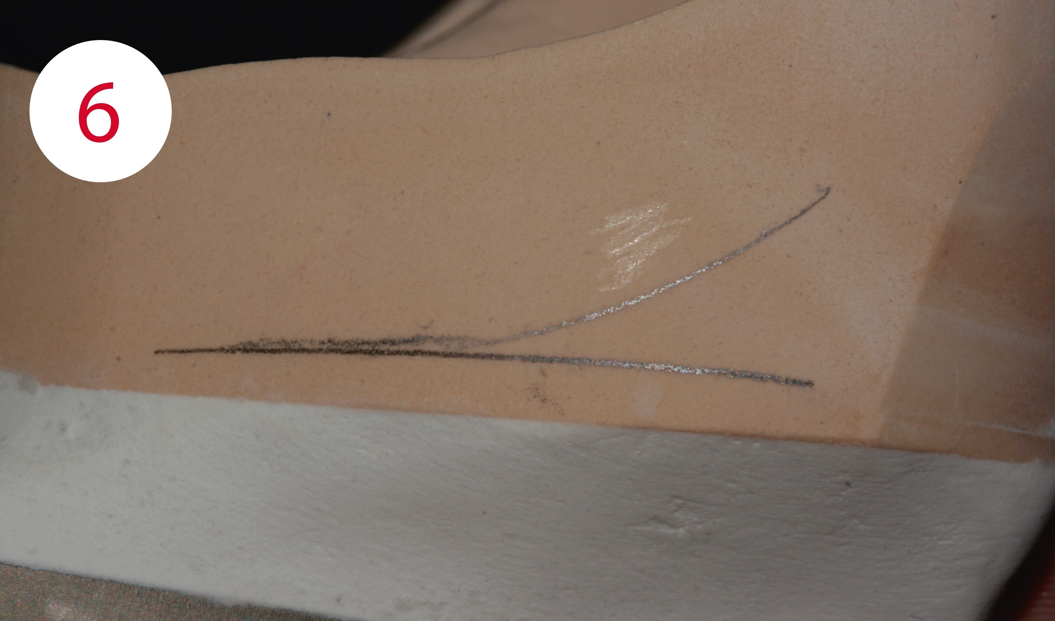
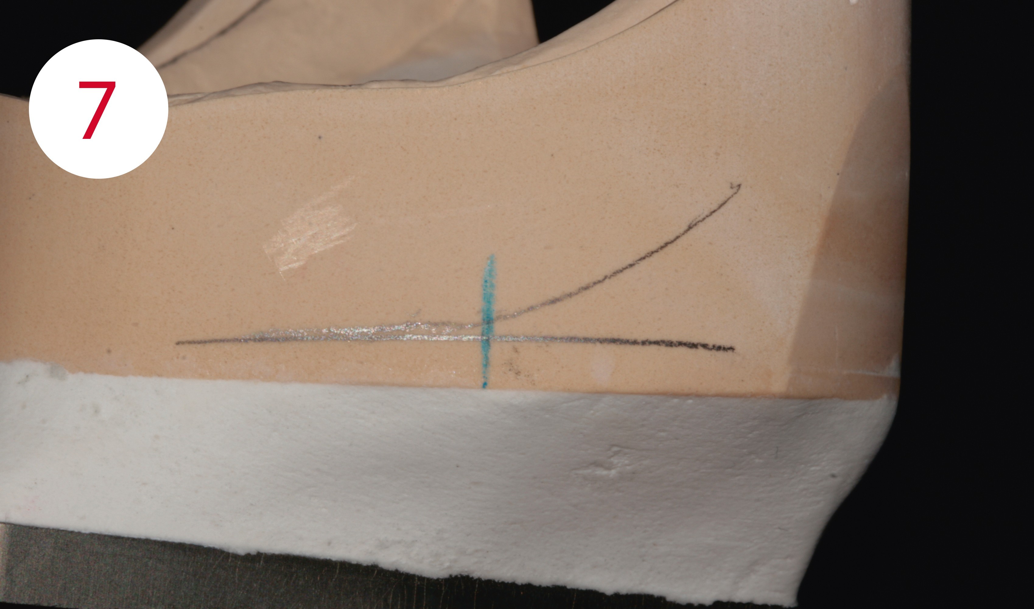
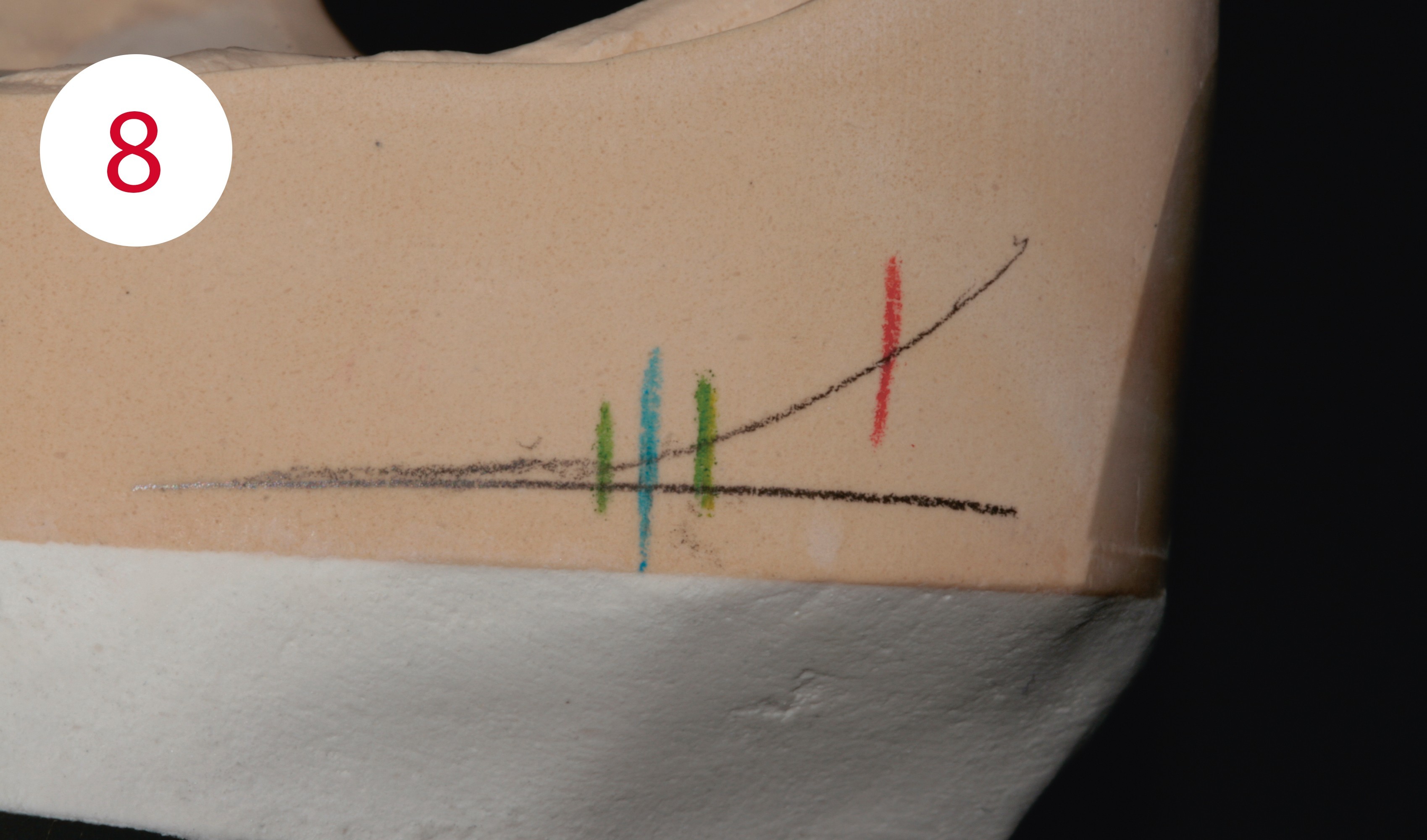
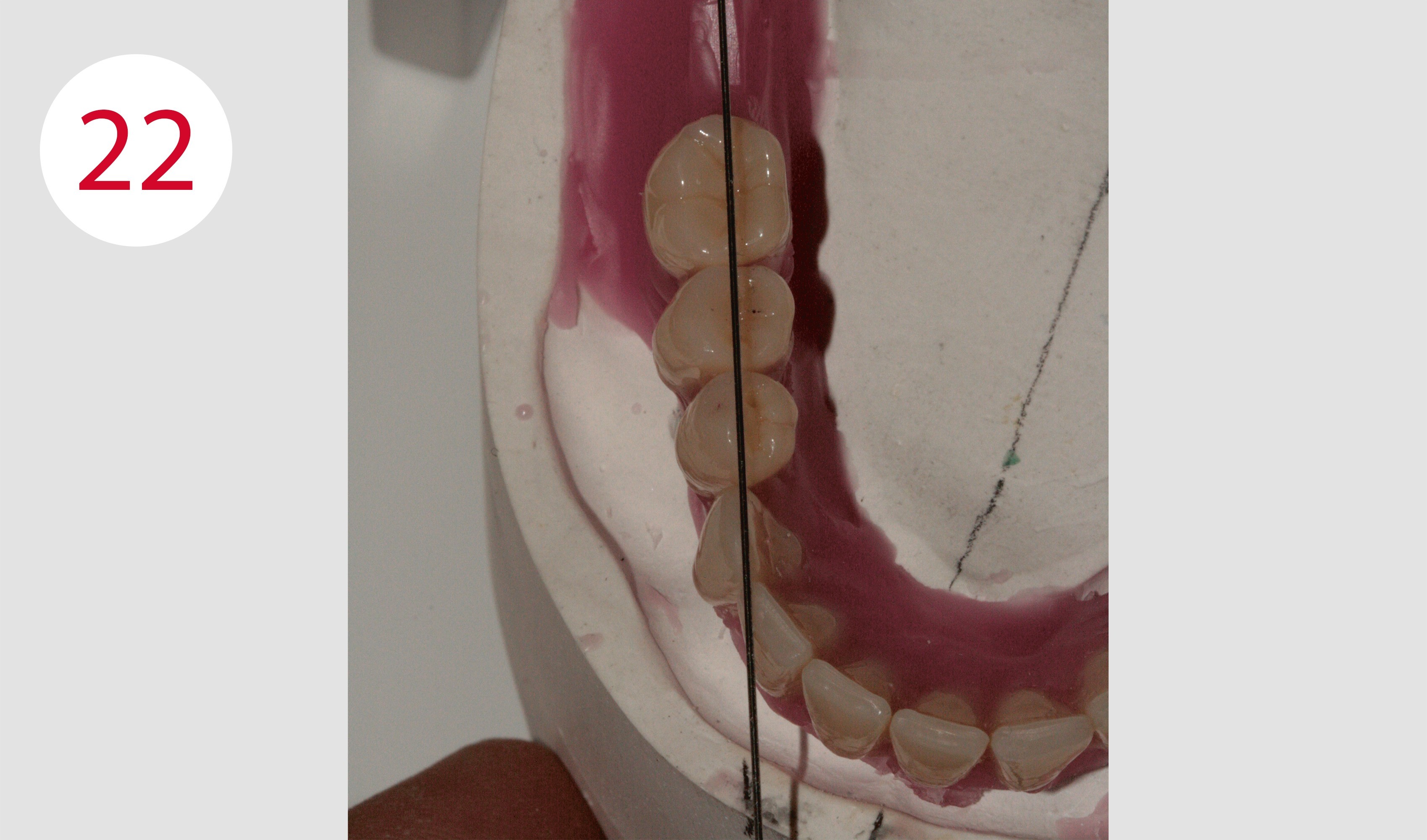
To determine the masticatory center, the contour of the alveolar ridge is transferred to the outside left and right of the model using the profile compass. (Fig. 5). At the lowest point of the posterior region, a line is drawn parallel to the Camper's plane with the ruler (Fig. 6). The area of the largest masticatory unit, the masticatory center, is positioned at the intersection of both lines – the lateral ridge contour and the Camper's plane or table level (Fig. 7). To the right and left of the marked masticatory center, a tolerance range with a maximum distance of 2 mm is also plotted with vertical lines. Then the stop line is defined; and no tooth with contact to the antagonist is set up dorsally of the line. This is determined by applying a 22.5° angle measure to the marked masticatory center and the distally located intersection of the angle with the contour of the alveolar ridge where it forms the position of the stop line (Fig. 8).
Fig. 5: Transfer of the lower alveolar ridge contour with the profile compass
Fig. 6: Point of intersection between the lateral contour of the alveolar ridge and Camper's or the plane of occclusion
Fig. 7: Position of the largest masticatory unit (masticatory center)
Fig. 8: Stop line and tolerance ranges for the sagittal position of the largest masticatory unit


SETUP OF THE UPPER ANTERIOR TEETH
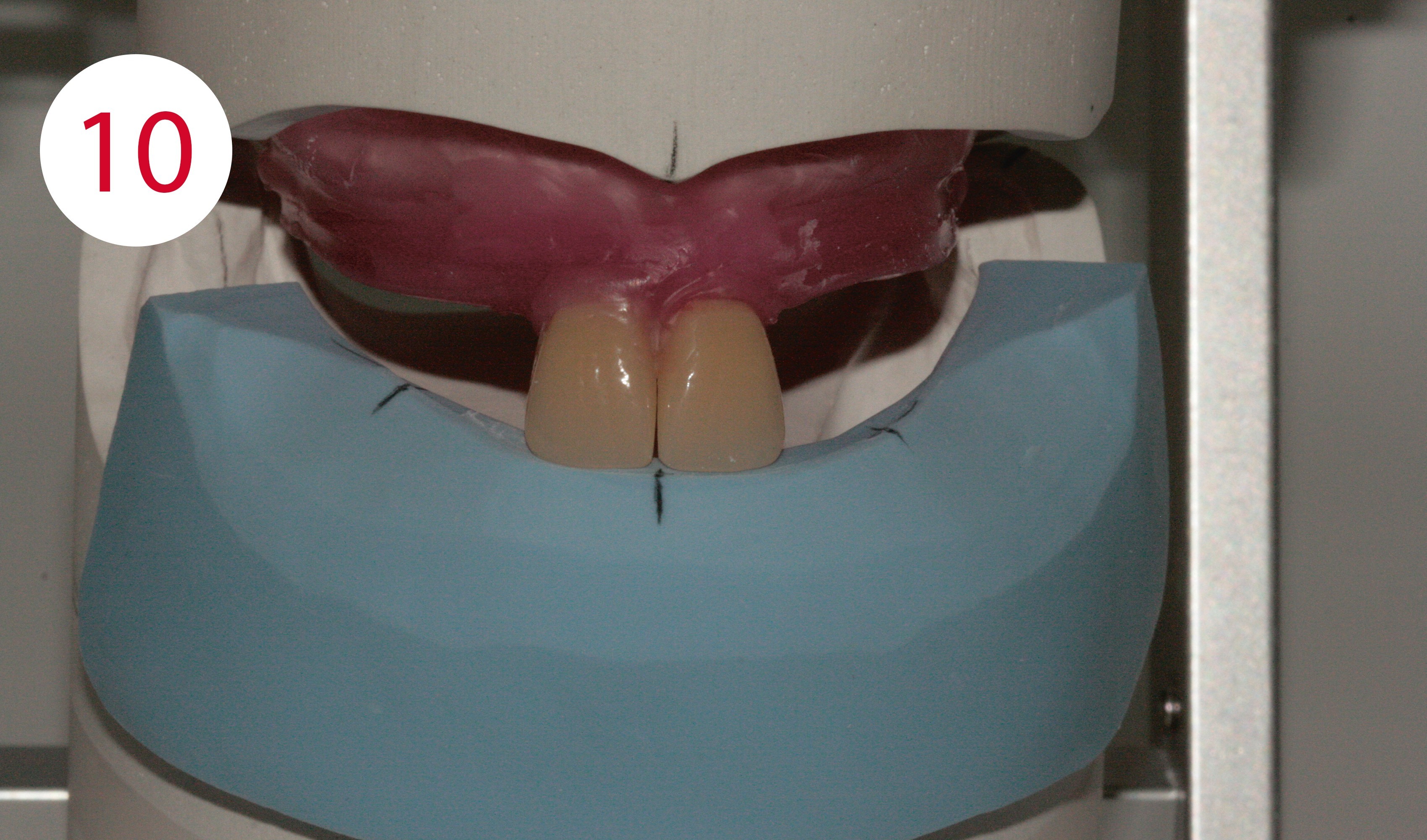
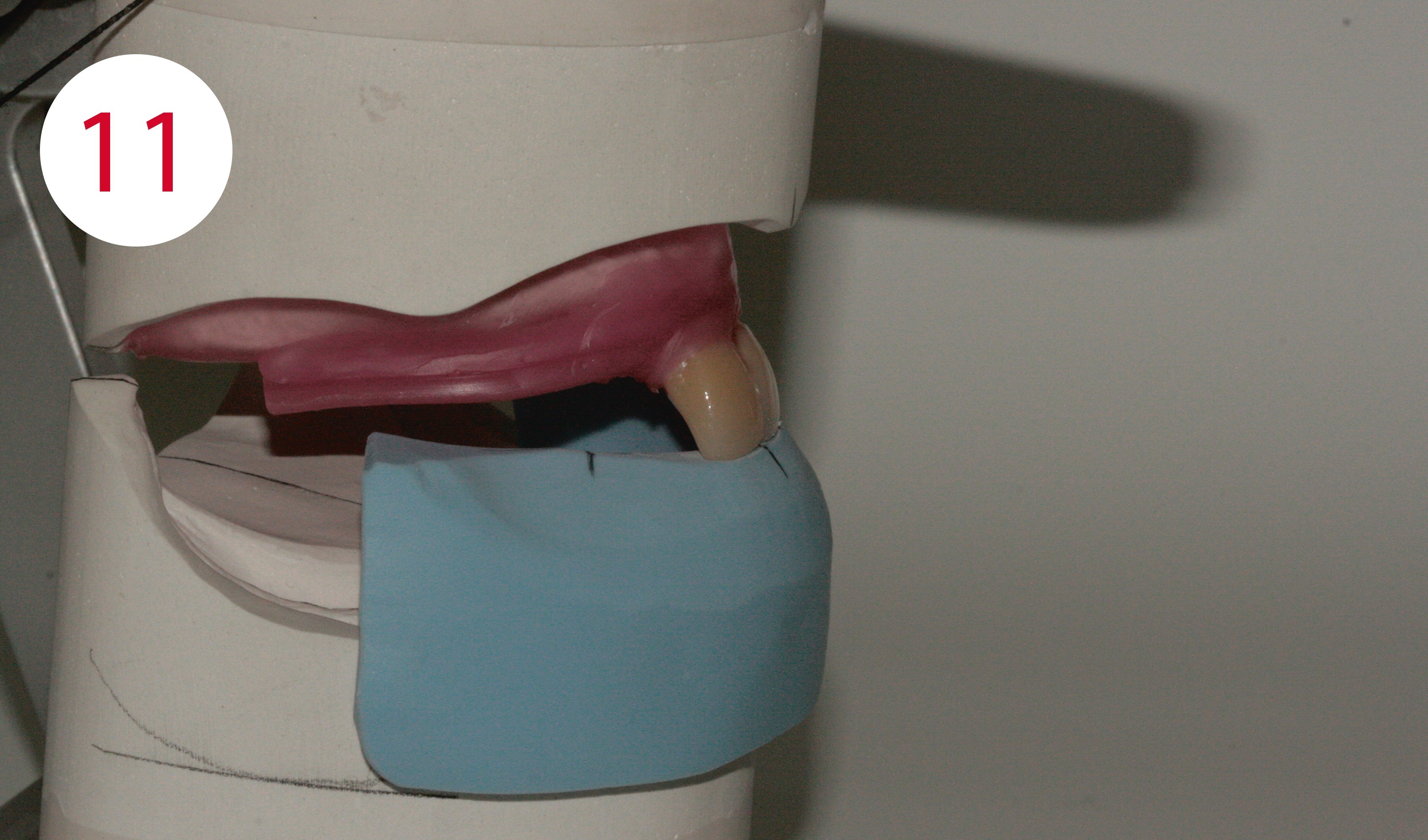
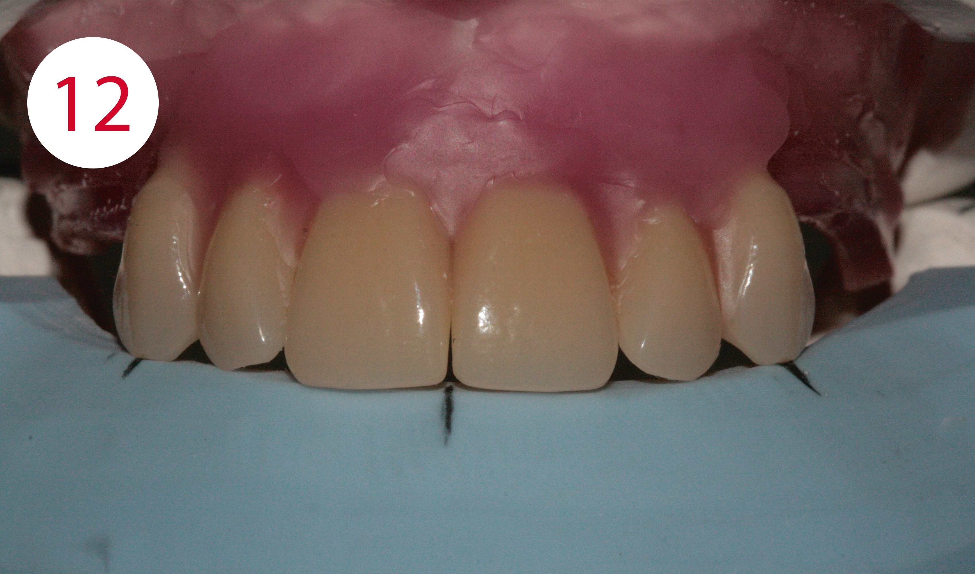
For the setup with PhysioStar NFC+ anterior teeth, a silicone key is first fabricated from the provided esthetic control template. All markings of the esthetic control template, such as occlusal plane, midline, canine points, smile line, maximum vestibular position of the posterior buccal surfaces are transferred to this (Fig. 9). Teeth 11 and 21 are now positioned so that their cutting edges are flush with the anterior edge of the silicone key and the central line is perpendicular between the two centers (Figs. 10, 11). If the two central incisors are in the correct position, the two upper canines are positioned such that their tips point to the canine marking, whereby their labial axes are positioned slightly mesial. In the proximal view they are inclined inwards with their cutting edges and outwards with the neck of the tooth. To achieve a natural-looking "deviation", teeth 12 and 22 are slightly twisted and positioned slightly higher incisally than the middle incisors (Fig. 12).
Fig. 9: Silicone key of the esthetic control template, transfer of data
Fig. 10 and 11: Alignment of the central line on the silicone key
Fig. 12: Canine tooth positions aligned on the silicone key
SETUP OF THE LOWER ANTERIOR TEETH
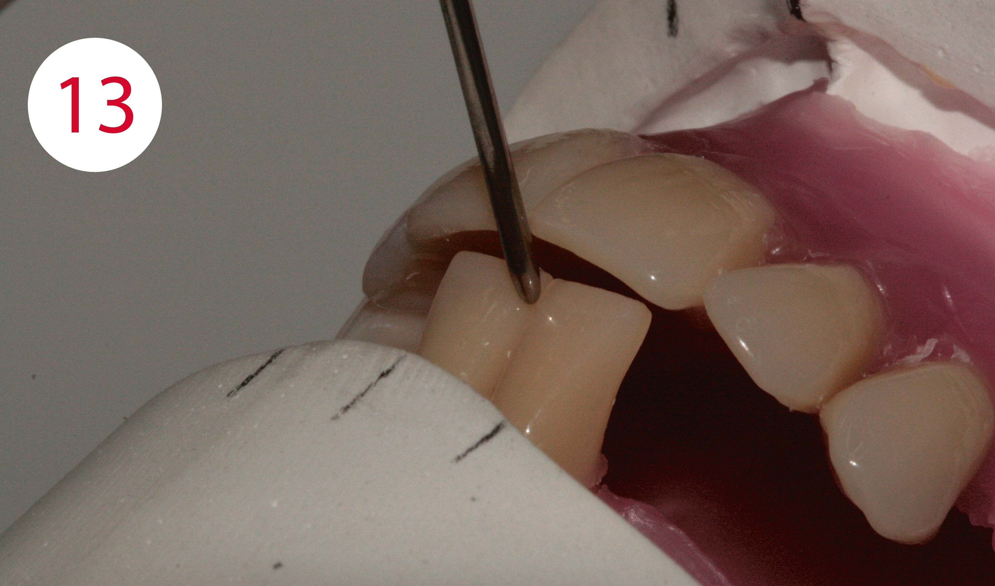
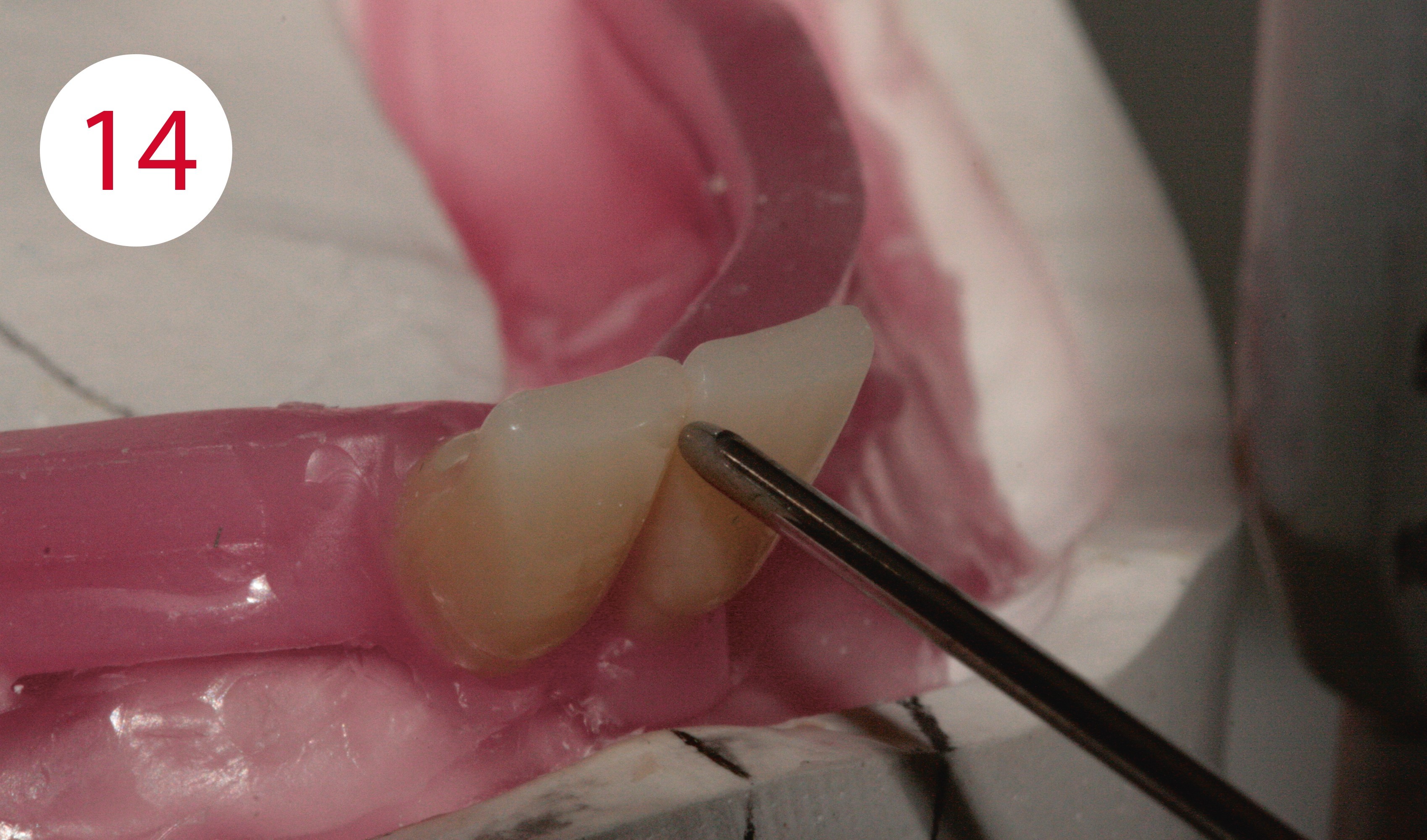
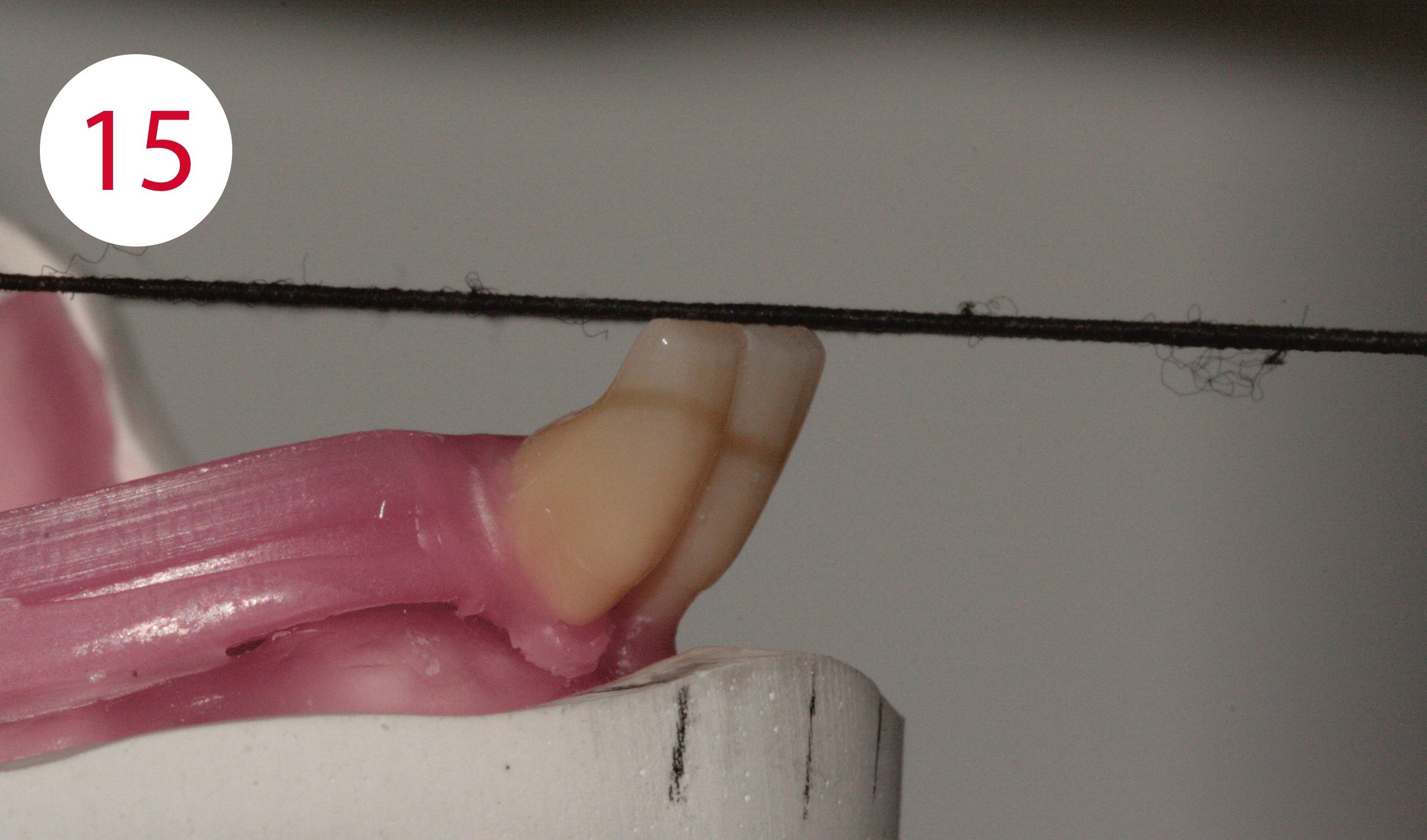
The two central lower incisors, 31 and 41, touch the incisor pointer with their mesial edge at the level of the rubber of plane of occlusion. Their vestibular surfaces touch the front edge of the silicone key to reflect the shape of the lower lip support as determined on the patient using the esthetic control template (Figs. 13, 14, 15).
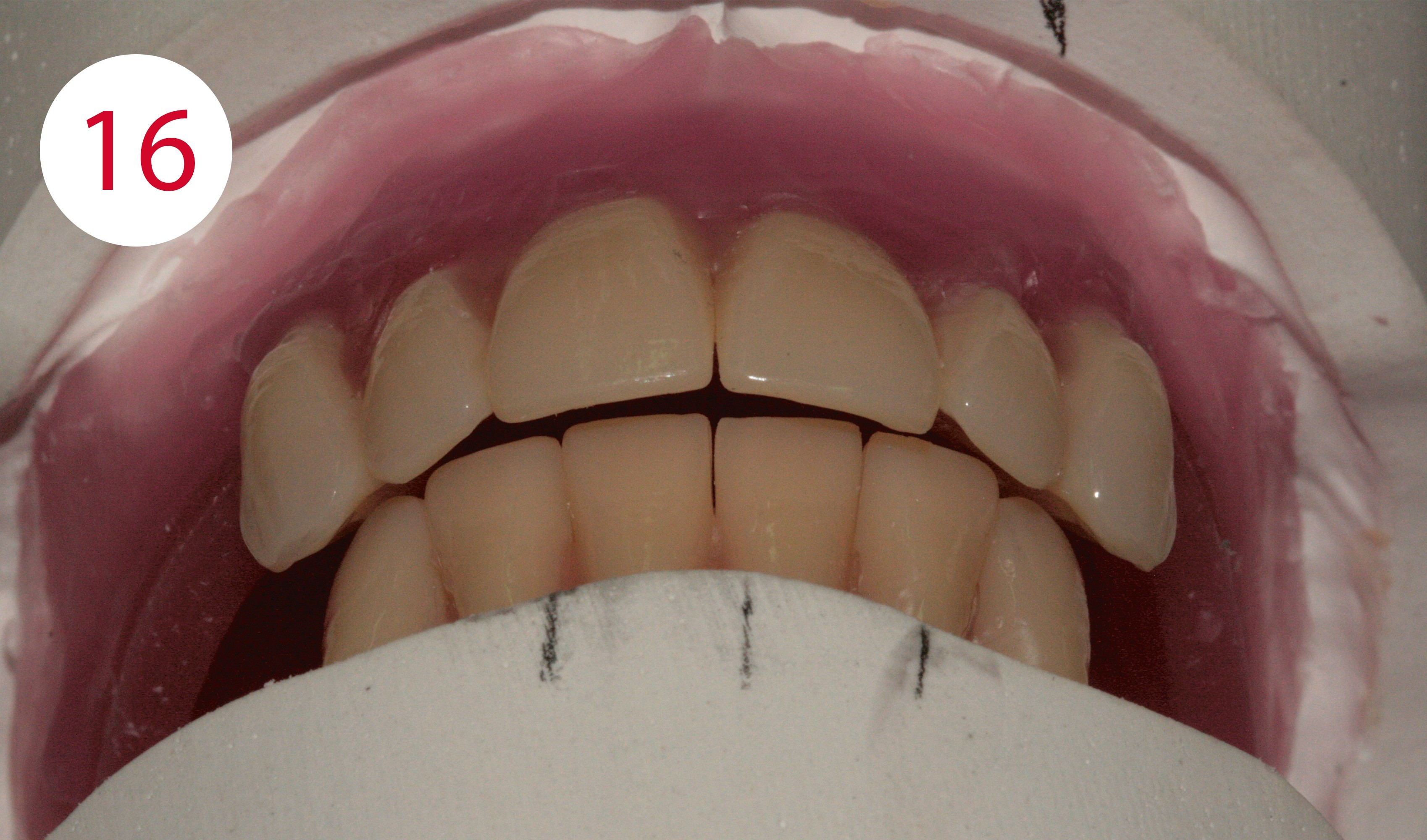
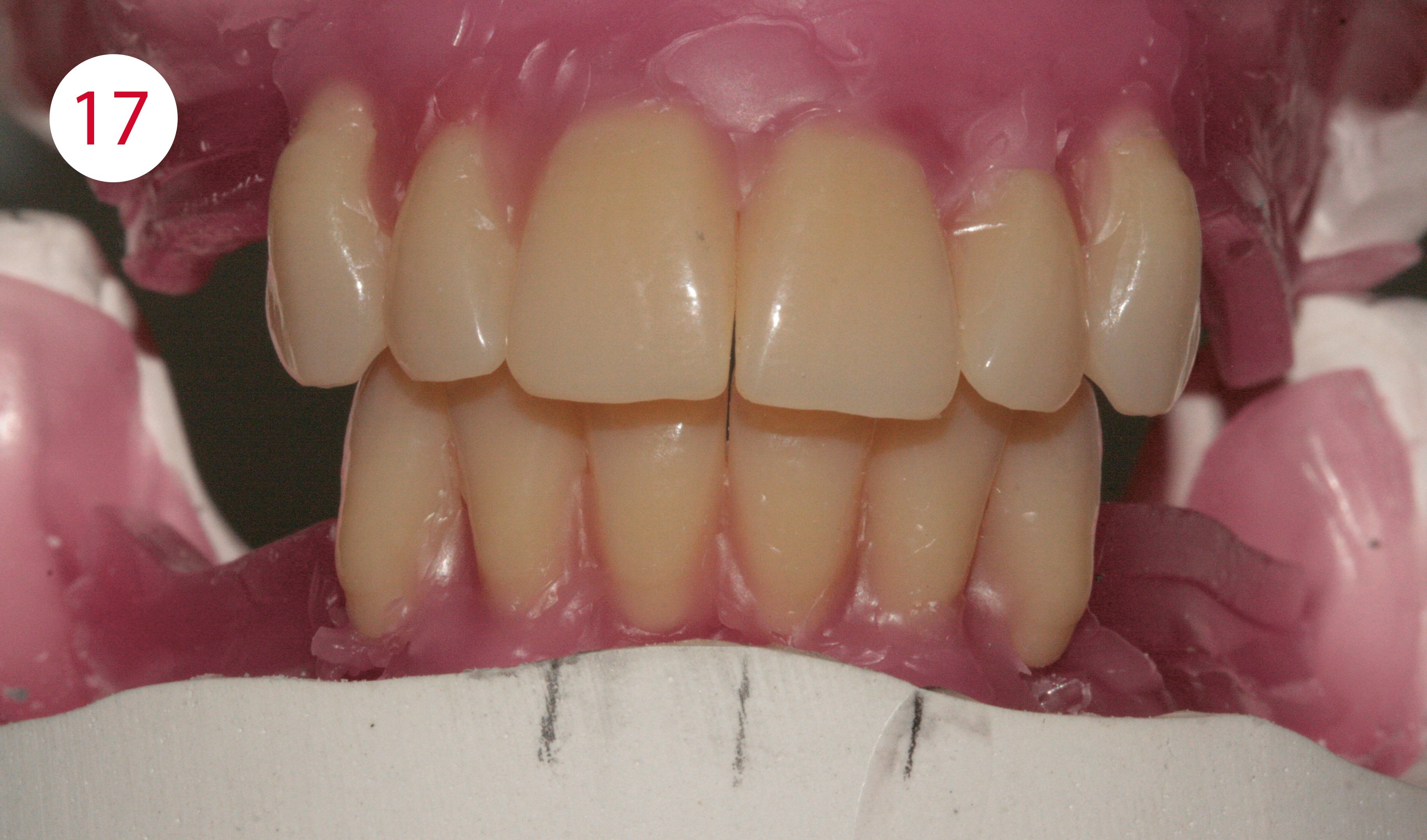
Overbite and overjet depend on several factors. A well-known rule of thumb is that the overbite and the sagittal step are 1 mm each. Rules of thumb imply a solution based on average values that may be correct, but do not have to be. Here, only the dentist can determine correct physiological information relating to the case on the patient and provide this to the laboratory in the form of the esthetic control template and the silicone key fabricated there (Figs. 16, 17).
Position teeth 42 and 32 with their incisal edges traversing the rubber band and their vestibular surfaces touching the silicone key. The tips of the lower canines, teeth 33 and 43, protrude about 0.5 mm above the rubber band. Their axis is slightly inclined mesially, their mostly distal cutting edge contour is aligned with the static lines.
Fig. 13, 14, 15 and 17: Setup of teeth 31 and 41
Fig. 16: Overjet reconstructed according to the silicone key


SETUP OF THE LOWER POSTERIOR TEETH
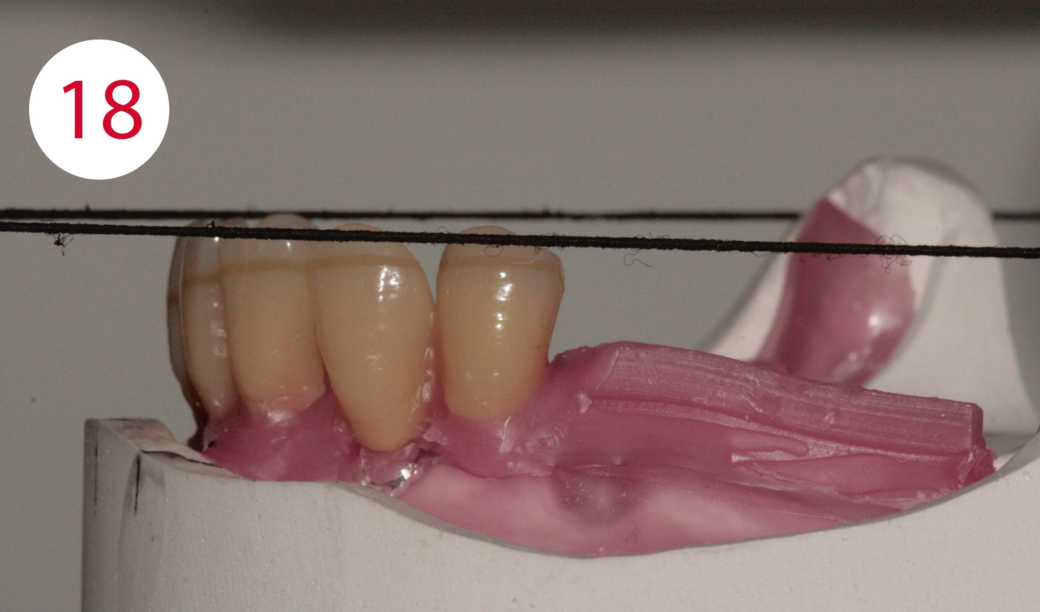
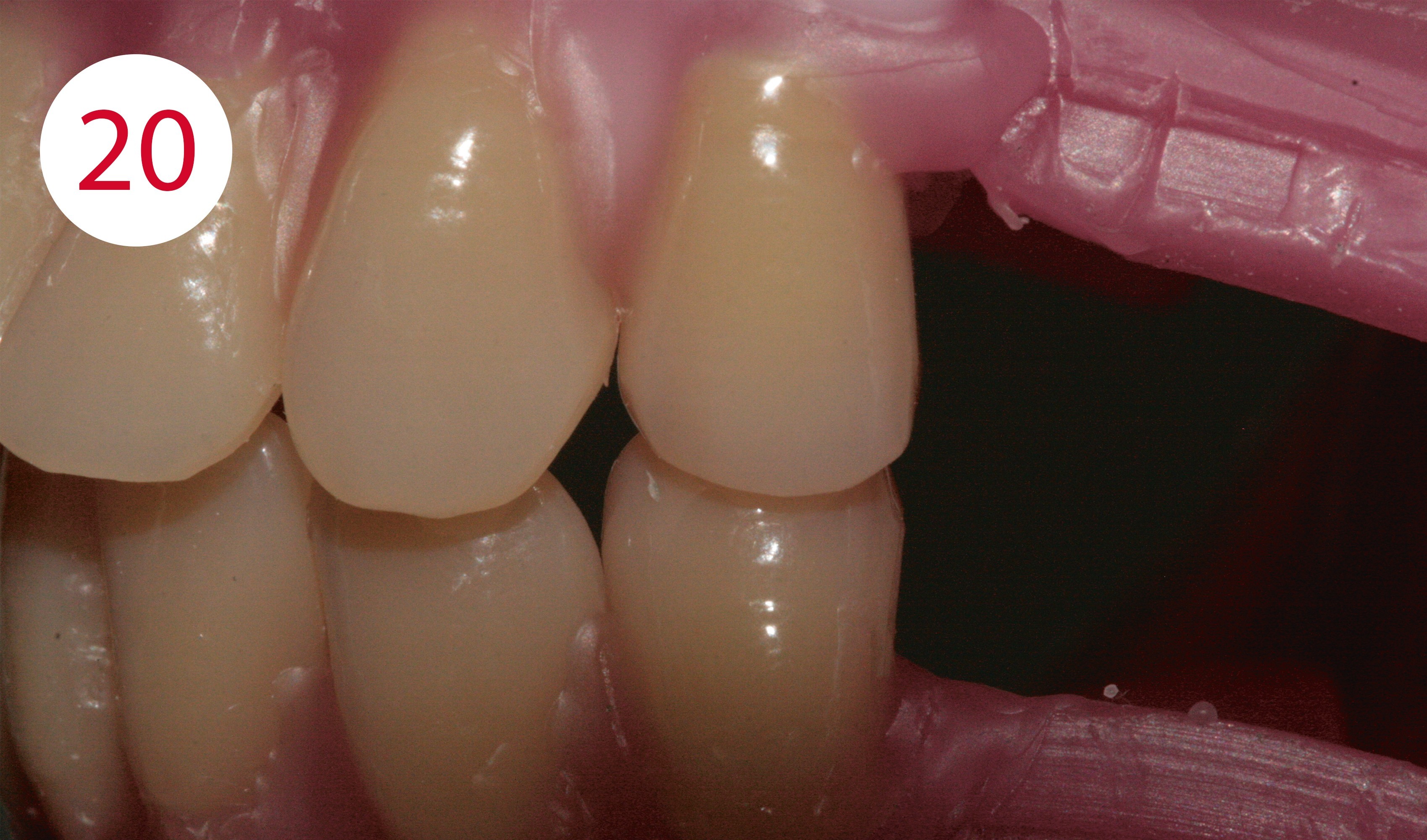
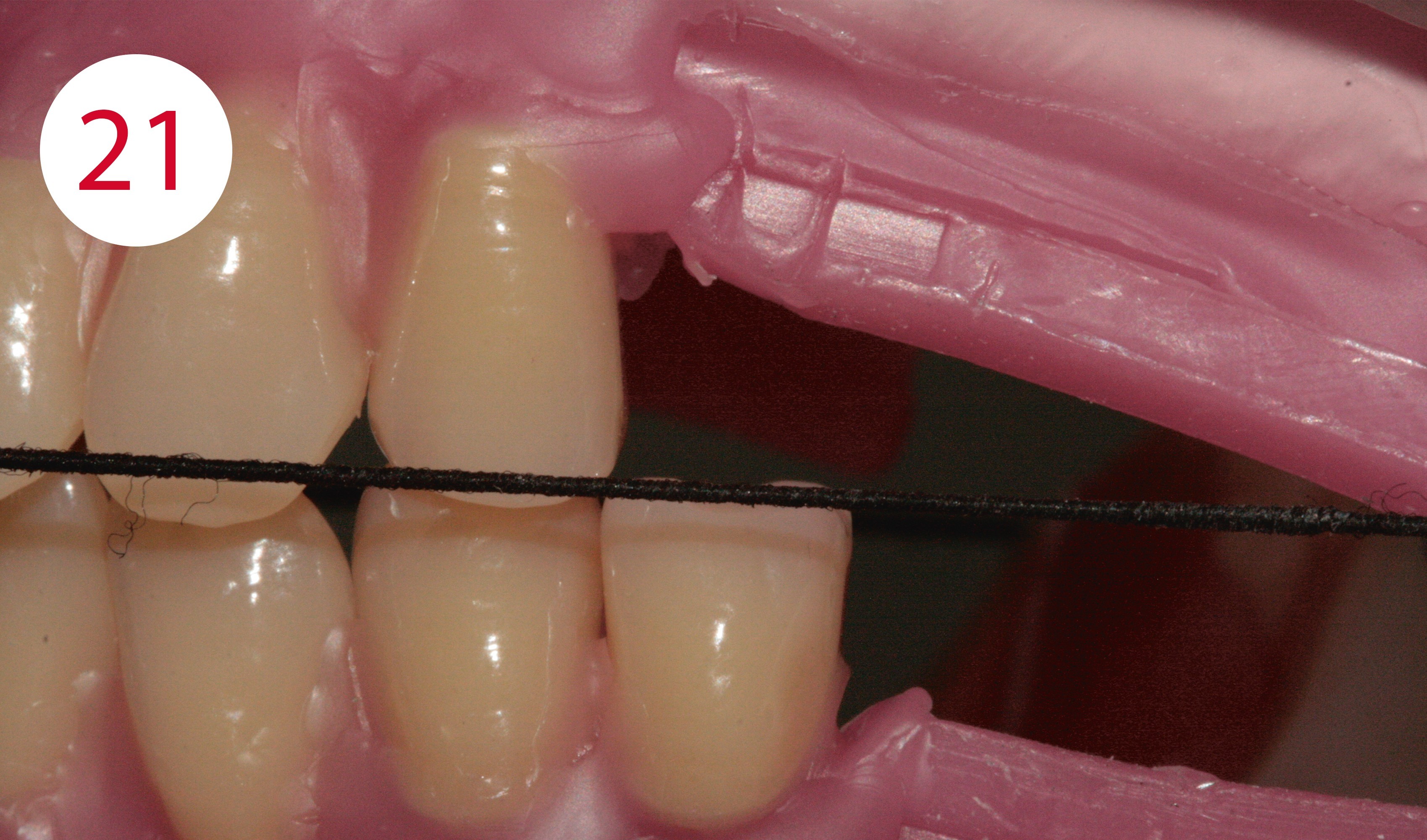
These are set up according to the GERBER method in tooth-to-tooth relationship. Posterior teeth such as the Condyloform II NFC+, which have a very pronounced centric fossa in the lower jaw and correspondingly large support cusps in the upper jaw according to the mortar-pestle principle are appropriate for this purpose. One starts with teeth 34 and 44. Their buccal cusps positioned on the static line and slightly protrude above the plane of occlusion (Figs. 18, 19, 20). Their axes are slightly inclined distally. Teeth 35 and 45 are positioned such that both cusps are at the level of the plane of occclusion (Fig. 21). Their central fissure is positioned on the static line and their axes are also slightly inclined to distal. Due to the spatial conditions, the first lower molars, 36 and 46, were placed after the second lower premolars. The first lower molars each stand on the static line with their central fossa in the area of the marking of the masticatory center (Fig. 22). Viewed from buccal, the mesial cusps are positioned at the level of the the plane of occclusion, the distal cusps slightly above (Fig. 23). In this case, the determined stop line did not allow the setting up of second lower molars.
Fig. 18: Buccal cusps of the lower first premolars extend slightly above the occlusal plane ...
Fig. 19: … and are positioned on the static line
Fig. 20: Tooth-to-tooth relationship of the first premolars
Fig. 21: Teeth 35 and 45 are at the level of the occlusal plane with both cusps
Fig. 22: The central fossa of the lower first molars are positioned on the course of the static line in the position of the masticatory center
Fig. 23: Viewed from buccal, the mesial cusps are positioned at the level of the plane of occclusion, the distal cusps slightly above
SETUP OF THE UPPER POSTERIOR TEETH
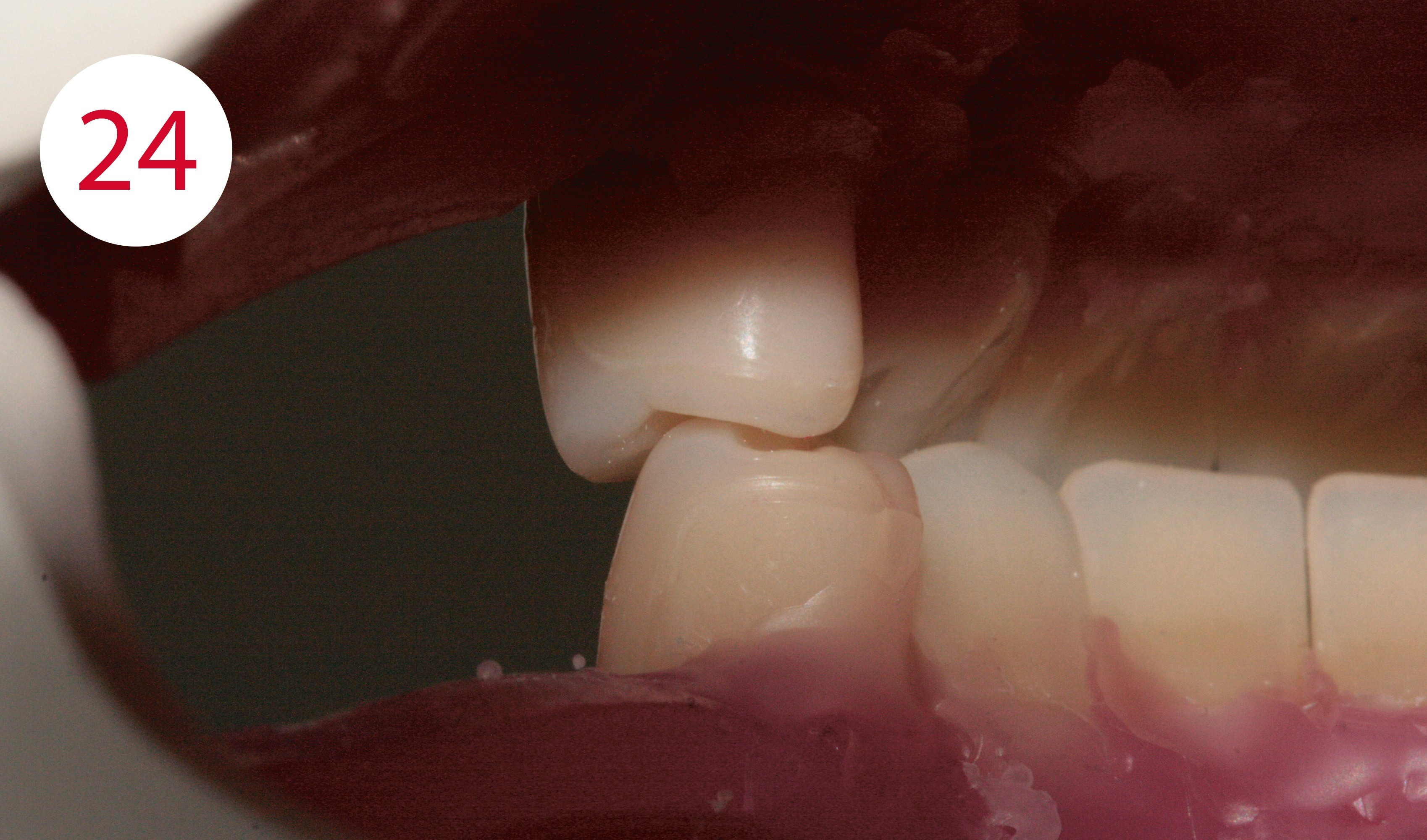
Next, the upper posterior teeth are set up. Here one starts with teeth 14 and 24, which occlude with teeth 34 and 44 in a tooth-to-tooth relationship. Their axes are slightly inclined distally. The buccal cusps of the lower antagonists (1:1 relationship!) each have contact in the mesial fossa of the upper premolars. The palatal cusps may have slight contact with the distal ones (Fig. 24).
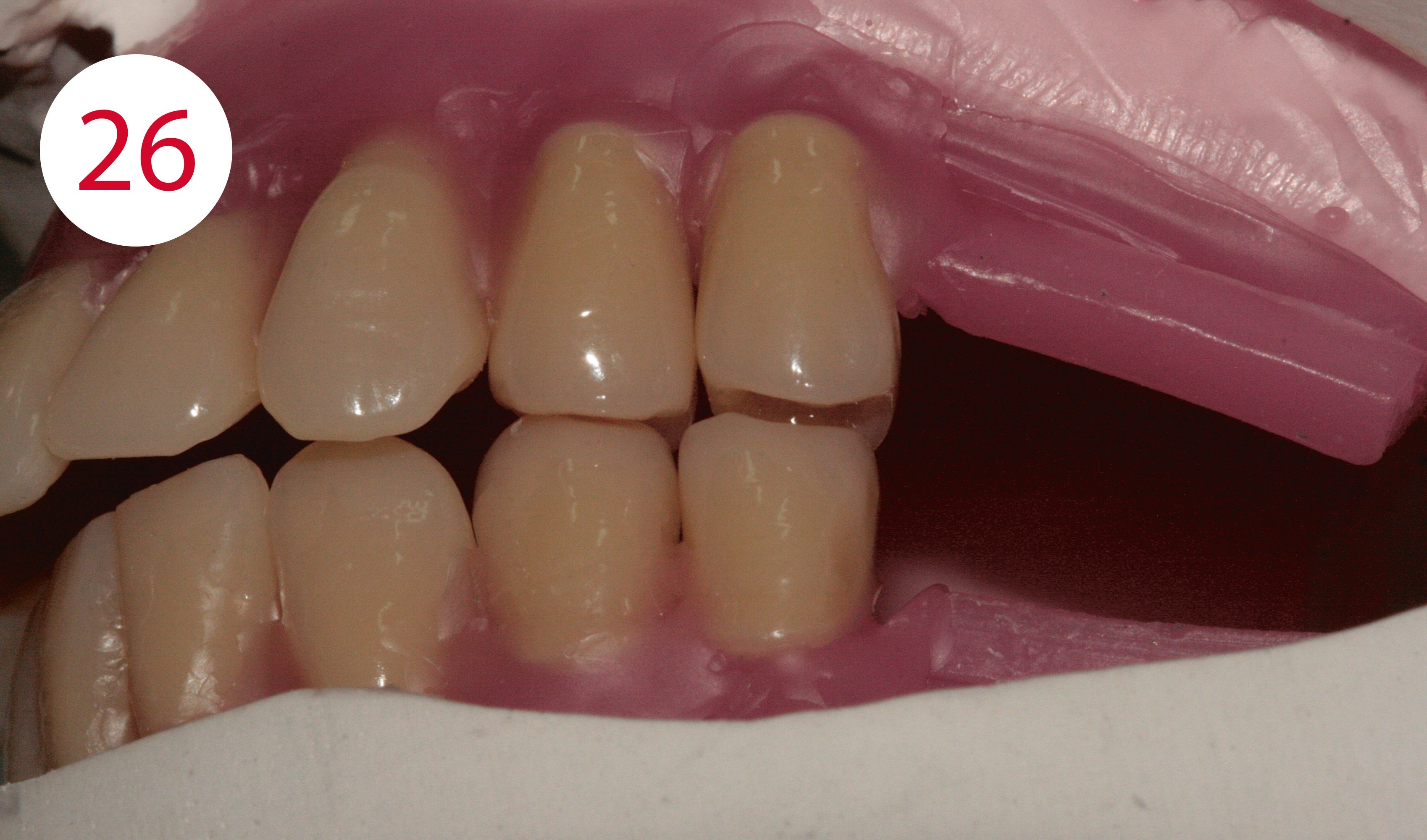
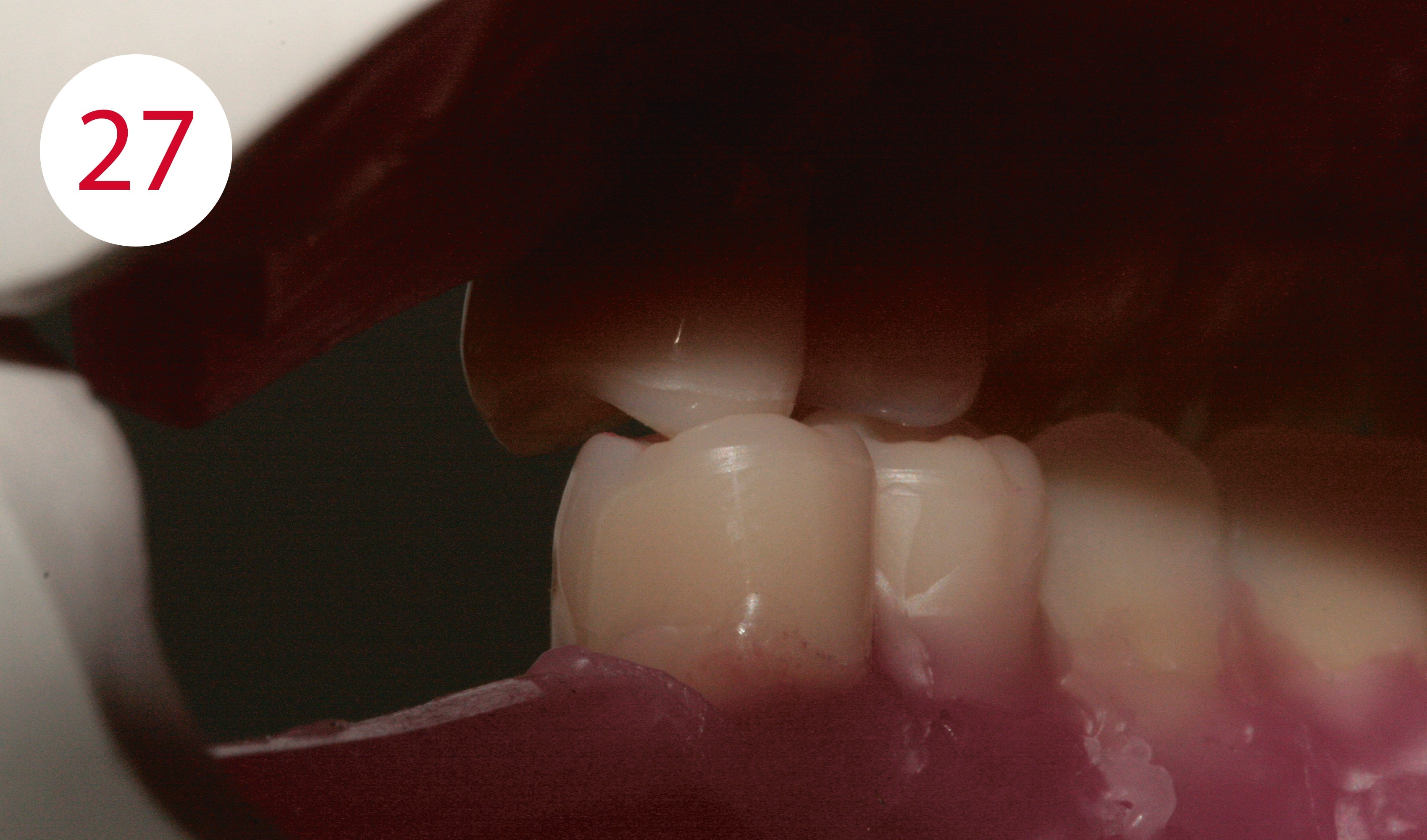
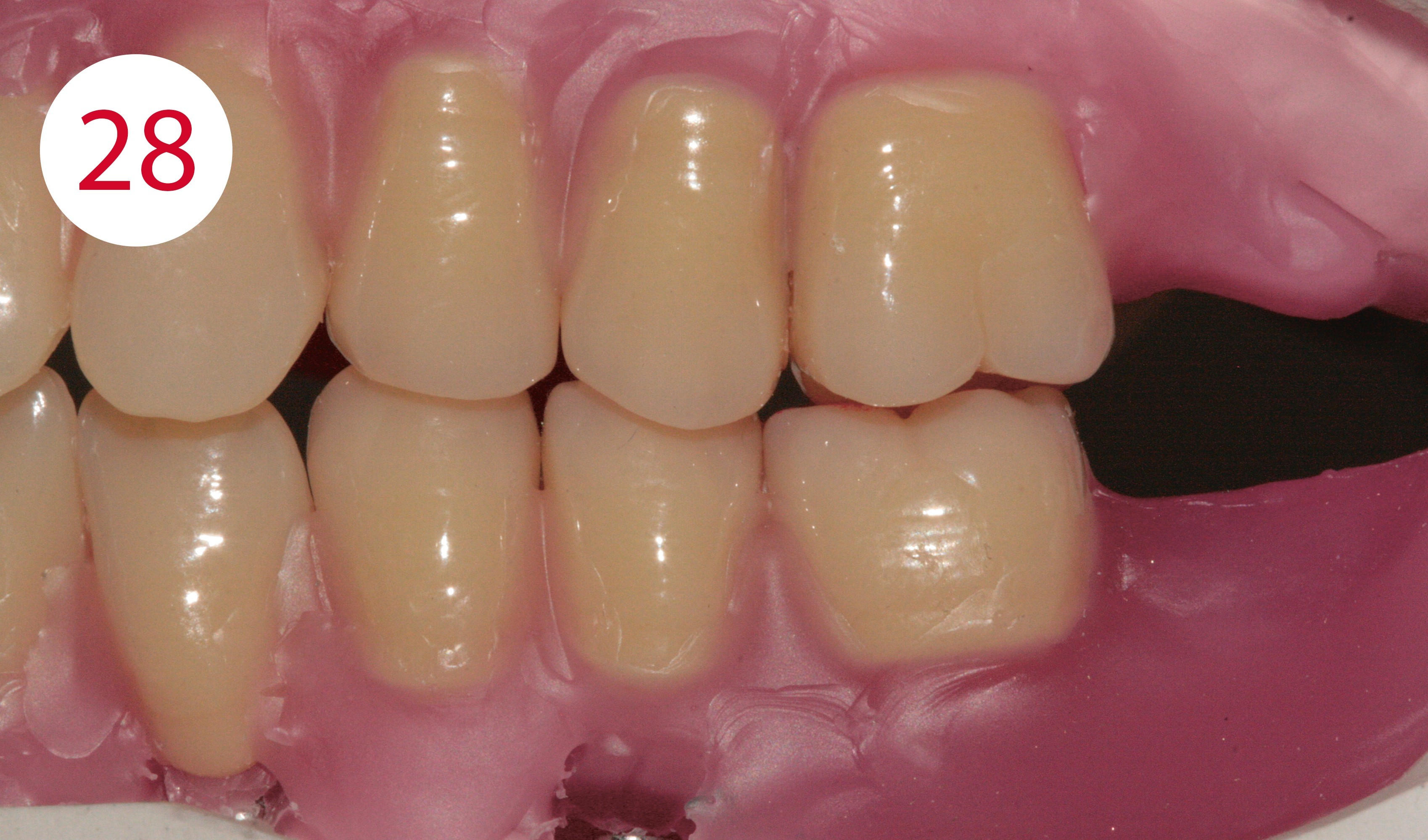
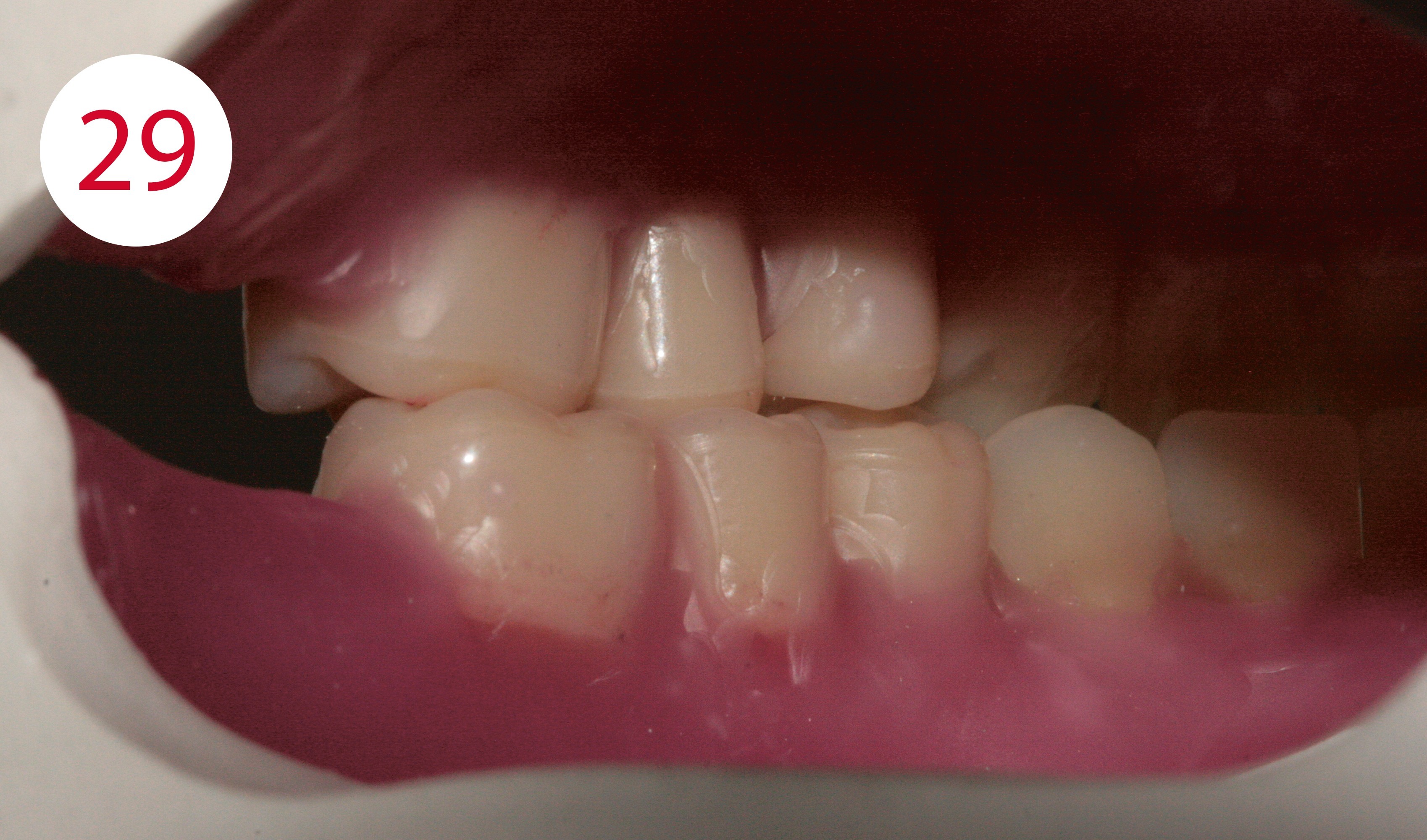
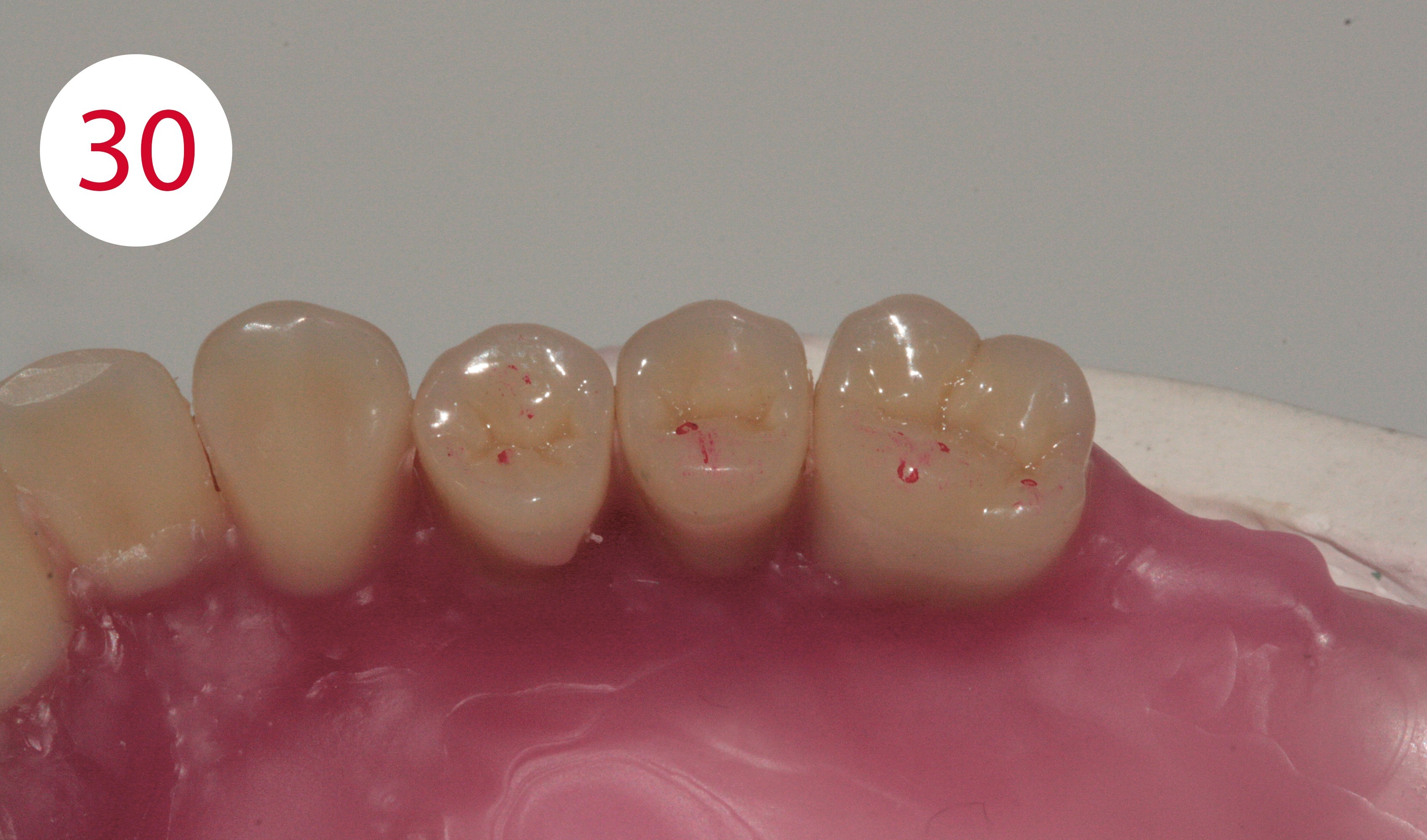
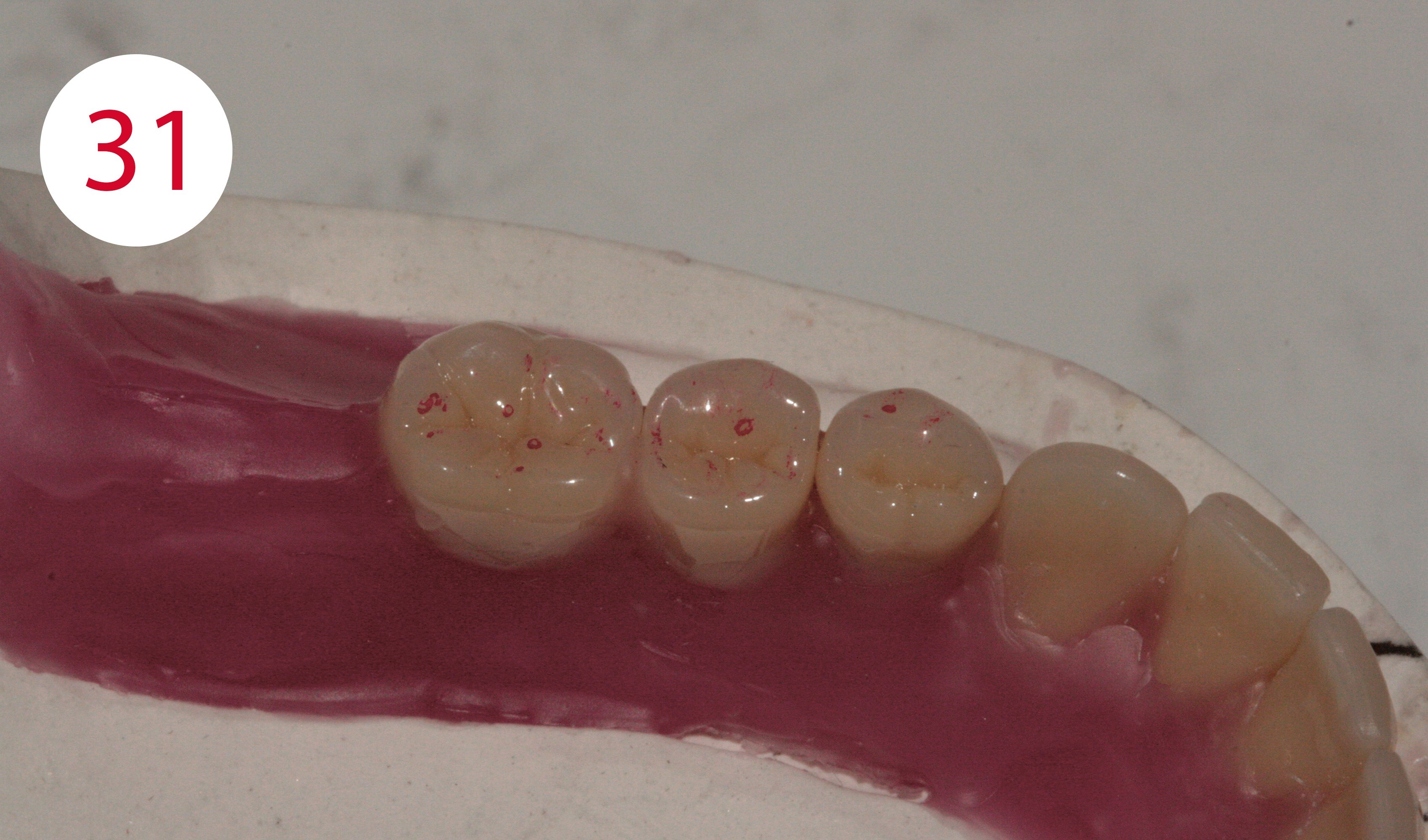
Teeth 15 and 25 are set up vertically or with minimal distal inclination (Fig. 25). However, the buccal cusps must not have any contact here (Fig. 26). Their palatal support cusps occlude in the fossa of teeth 35 and 45 (Fig. 27). When setting up teeth 16 and 26, care must also be taken that the buccal cusps are not in contact and that the mesiopala-tal support cusps occlude exactly into the fossae of the antagonists as central static support (Figs. 28-31). Excursion movements are only ground in after completion as a matter of principle. However, the centric or static contacts must already exist clearly and, if necessary, be ground in.
Fig. 24: According to GERBER: the buccal cusps of teeth 34 and 44 occlude in the antagonist
Fig. 25: Buccal position of teeth 15 or 25
Fig. 26: No buccal contact of the second upper premolars
Fig. 27: Support of teeth 15 and 25 only via the palatal cusps
Fig. 28: Tooth-to-tooth relationship
Fig. 29: Occlusal support of teeth 16 and 26 only palatal
Fig. 30: Static stops top
Fig. 31: Static stops bottom

MUSCLE-GRIPPING DENTURE BODIES
The denture bodies are modeled in a muscle-gripping manner. To this purpose, labial shields for the mouth ring muscle are fabricated in the top and bottom of the anterior region. In the posterior region, buccinator supports are created and the pull line direction (under muscle activity) of the cheek frenulum is tightened. The transitions from the teeth to the gingiva should not be too bulging and undercut ("pockets"), but rather more rounded and smooth at an obtuse angle.
FRAMEWORK FABRICATION LOWER HYBRID DENTURE
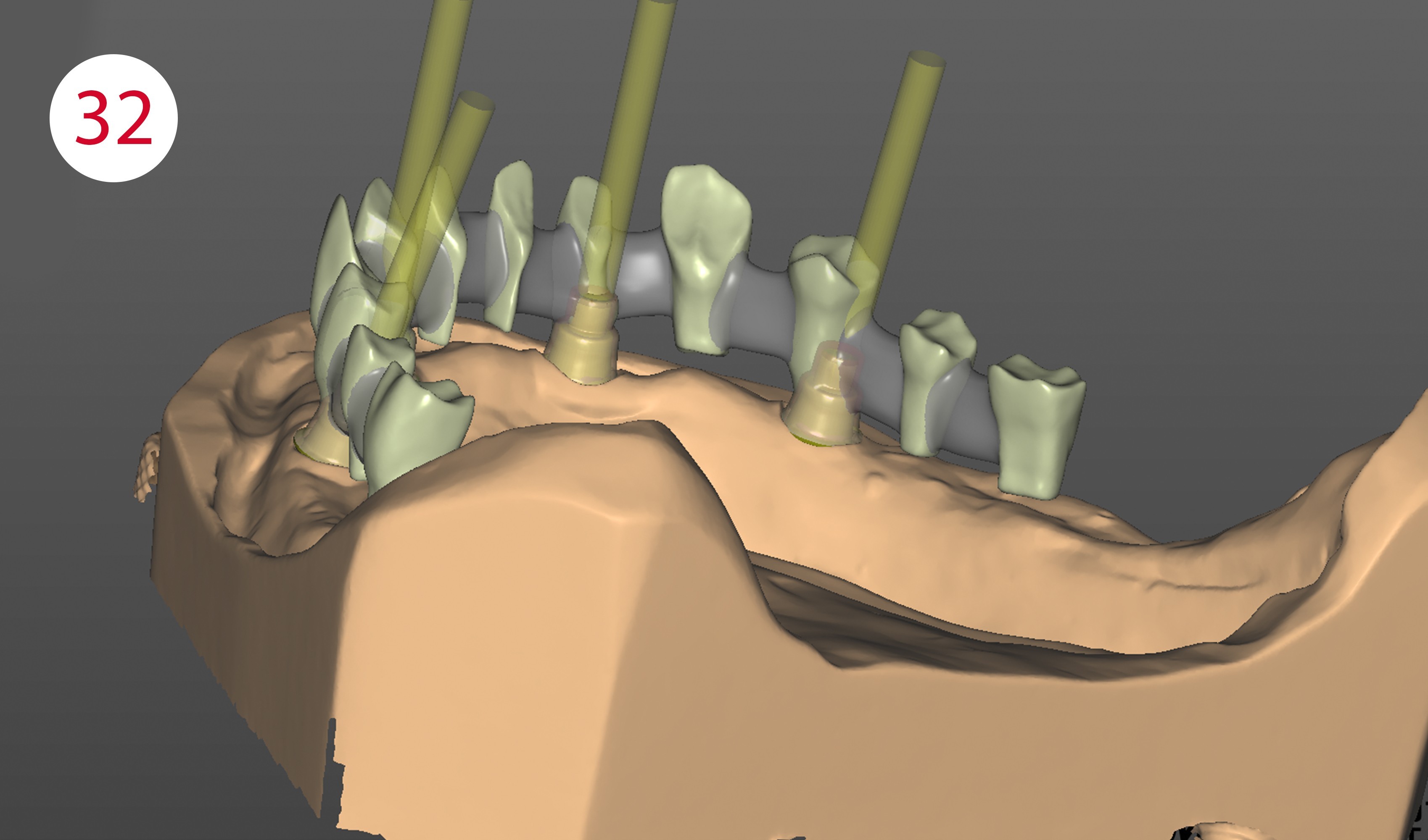
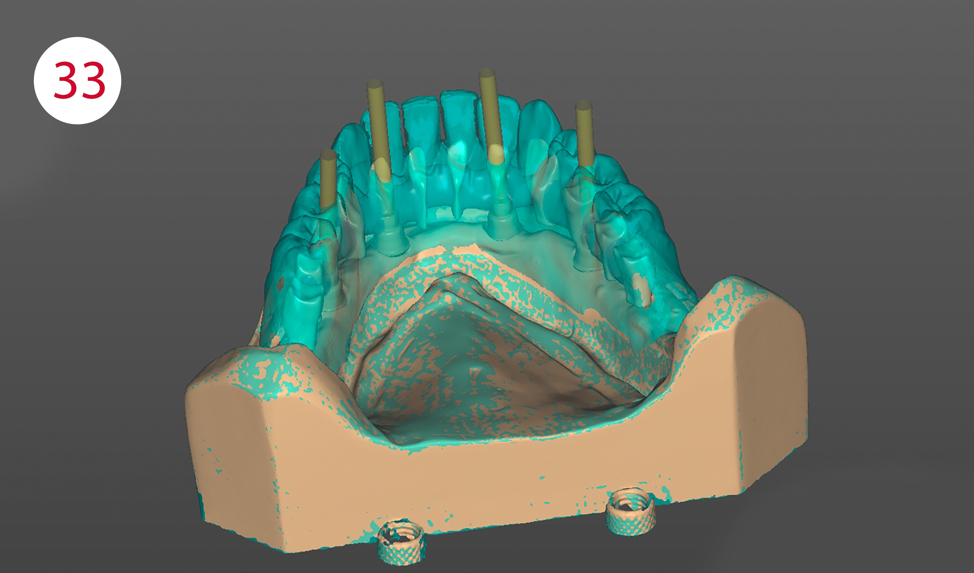
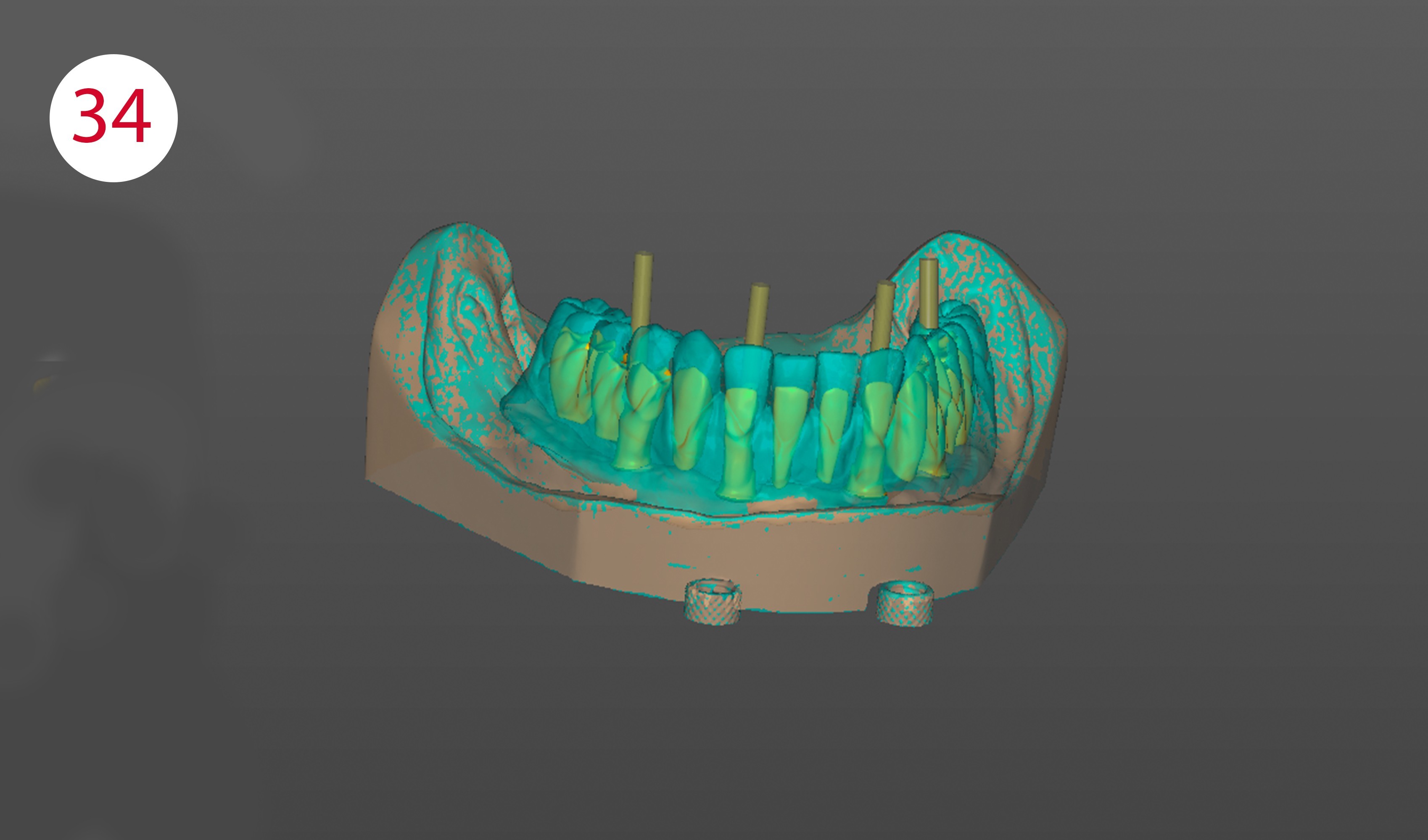
After completing the wax-up of the lower restoration, it is removed from the model and the scanbodies are screwed onto the implants. Then the model and the counter-bite (model with wax set-up) are scanned. Once the implant positions have been determined, the scanbodies are removed and the lower wax setup is placed on the model again and also scanned. Both models are then placed back in the articulator and the jaw relation is scanned. Once all the scans have been completed, one switches to the design software and constructs the metal framework (Figs. 32-34), which was then sent to Camlog (Dedicam) as a data set here. After receipt, the framework milled there is checked for surface quality and tension-free fit.
Fig. 32: Scan with scanbodies
Fig. 33: Scan with situation and/or wax set-up
Fig. 34: Designed framework with screw channels
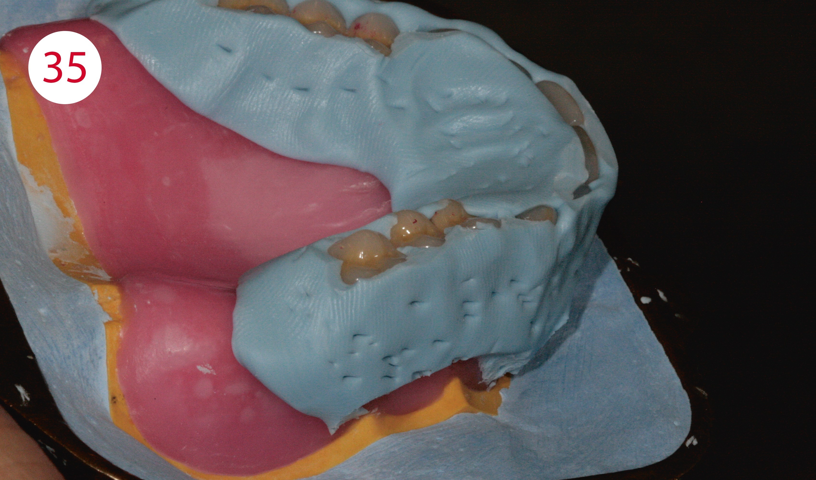
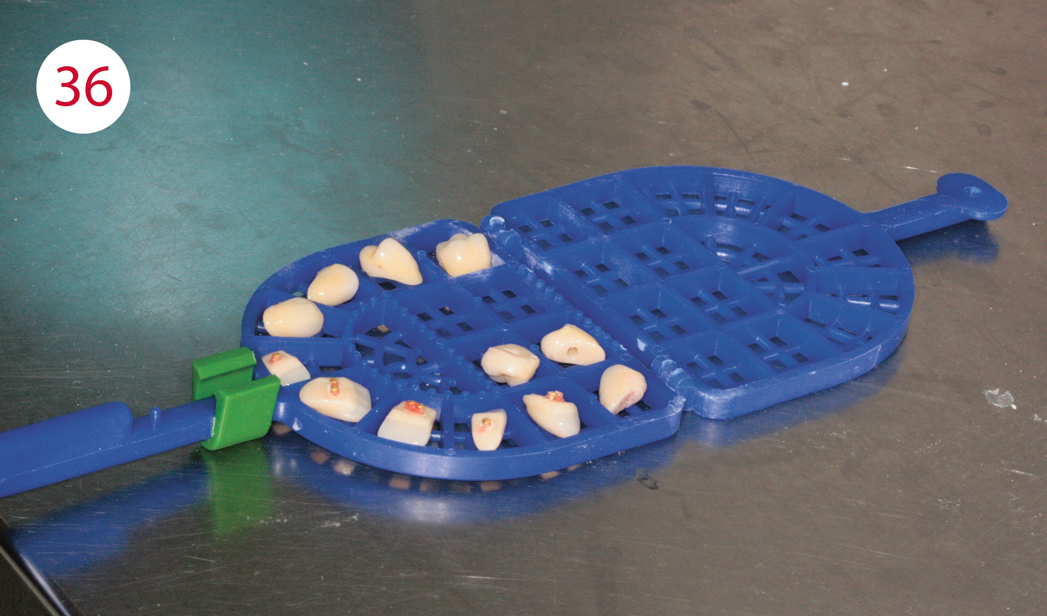
The metal construction is sandblasted and silanized. Then opaquer is applied. Once these steps have been completed, the wax-up is placed on the model and prepared for completion in the flask and then embedded. (Fig. 35). After the plaster has set, the flask is heated and opened. The softened wax can then be removed. The model is then steamed with clean, boiling water; the same applies to the teeth (Fig. 36). The basal contact surfaces of the teeth with the resin are roughened with a carbide cutter. Once the teeth have been placed back into the flask, they were conditioned basally with a silane. Prior to implementation in resin, the lower model was sufficiently watered for approx. 15 minutes, separated (Fig. 37) and the framework screwed on.
Fig. 35: Embedded wax-up of the upper full denture
Fig. 36: Teeth after steaming with clear boiling water
Fig. 37: Separating plaster versus resin

IMPLEMENTATION IN RESIN
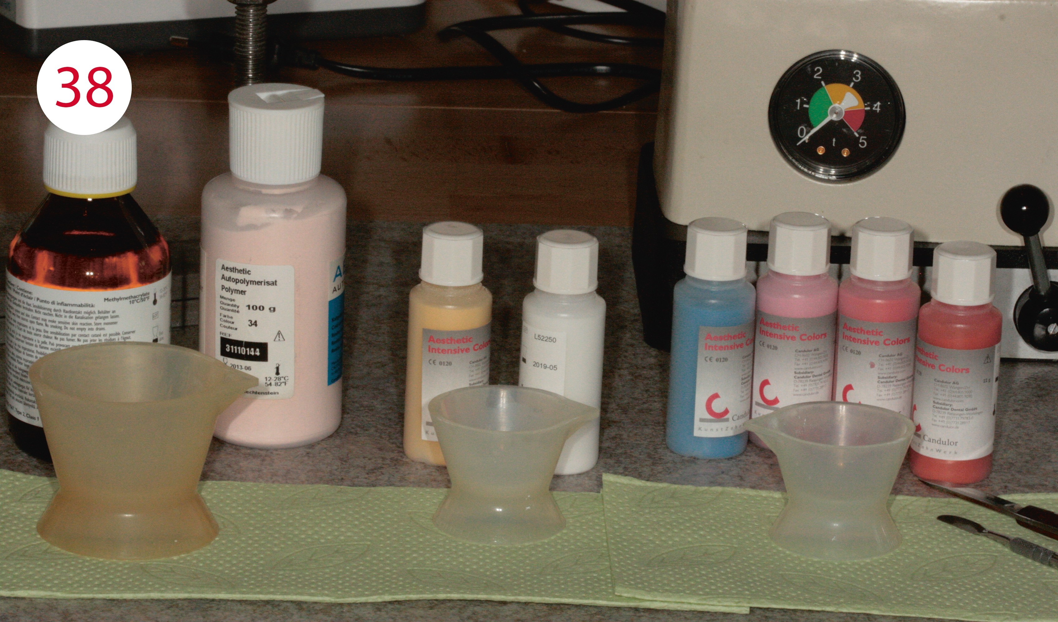
Before applying the resin and starting pressing, the components of the denture base resin are dosed, mixed and its swelling phase observed (Fig. 38). Shade 34 was chosen for the base. Shade 34 - mixed with a little yellow and white from the Aesthetic Intensive Colors range - was used in the area of the papillae and the modeled alveolar mounds. For the vestibular shield and the labial frenulum, shade 34 was mixed with RED, BROWN, BLUE and PINK and applied during the modeling phase of the resin in the sequence "papillae - lip shield - base". This meant first applying the resin mixture for the papillae thinly around the teeth with a spatula up to about 1/3 of the distance from the neck of the tooth.
In the second step, the resin for the vestibular shield was applied to the resin mixture for the papillae up to the vestibular fold. Nevertheless, the required mixing of both components for proper polymerization always has priority.
In the final step, the resin for the denture base in shade 34 was applied to the model and the teeth, then the flask was closed and placed in the press. After about 5 minutes under pressure, the bracket around the flask was closed tightly and placed in the pressure pot for 30 minutes. After completion of polymerization, divestment was performed. The models with the finished resin work were placed back into the articulator so that the static stops could be corrected and the excursion movements could be ground in.
Fig. 38: Preparation for completion in resin: everything was at hand, with cold-curing resin it is always best to cool both components
CENTRIC OCCLUSION
The first step is to focus on static or centric contacts. Should these not be present optimally after conversion into resin, they are ground in with a spherical diamond.
DYNAMIC OCCLUSION
After the centric stops, this is followed by dynamic occlusion, starting with laterotrusion. It is ground in by first unlocking both articulator joints and moving the support pin transversally on the support pin plate until the buccal cusps or the incisal edges of the canines are positoned above each other. It is important here that there is no canine guidance, as the buccal cusps would otherwise be relieved. With the aid of a green occlusion foil, laterotrusion was ground into the lingual cusp slopes of the lower posterior teeth. Due to the inverse mortar-pestle principle, the first premolars must be excluded from this. In the next step, the protrusion was checked with blue occlusion foil with the joints unlocked, and any interfering early contacts in the anterior region were removed. If there are excessively steep protrusion facets in the posterior region, they must also be removed. To grind in the retrusion, the locking screw provided for this purpose must be loosened on the articulator to simulate this short dorsally directed physiological movement, which is performed during swallowing.
FINISHING AND POLISHING
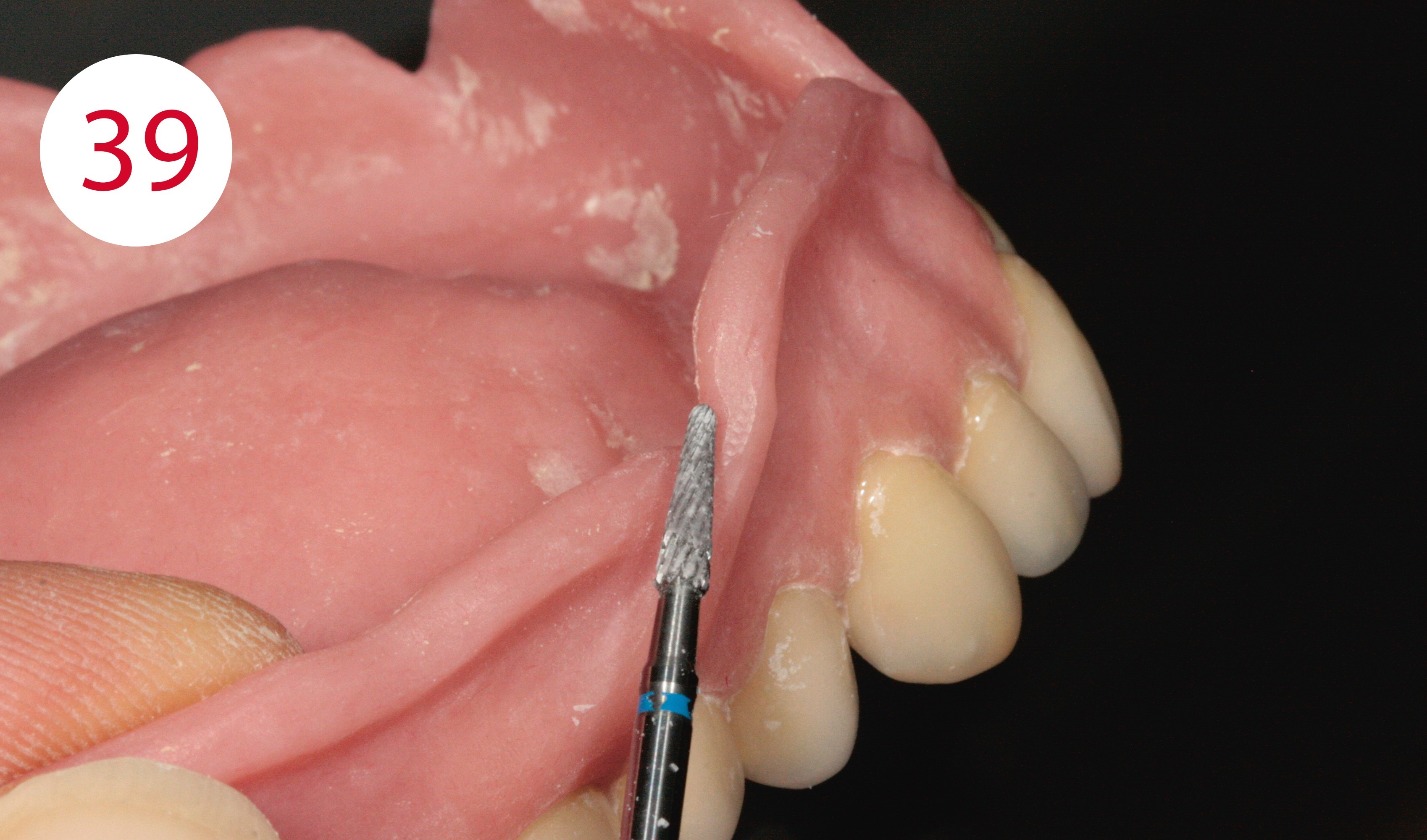
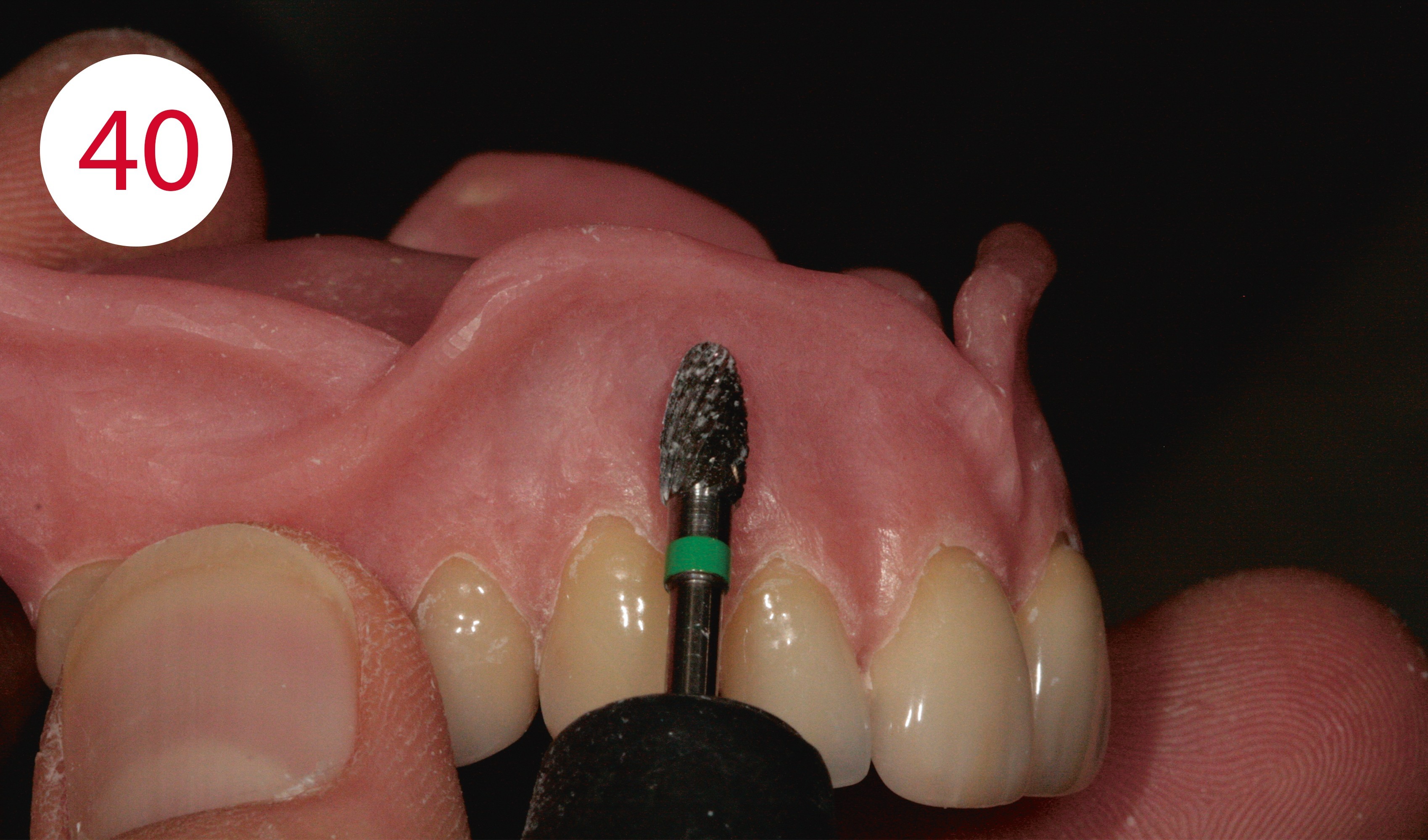
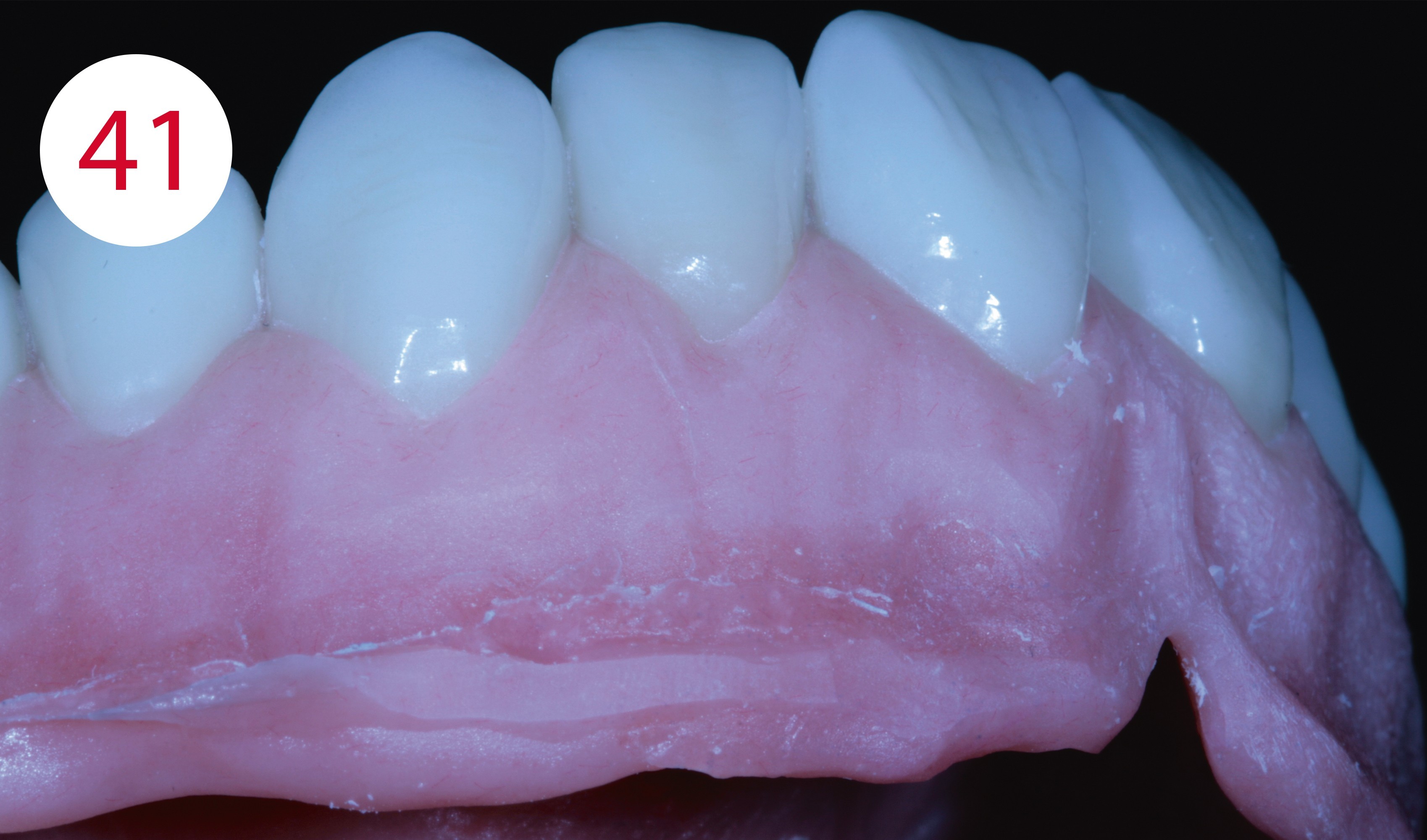
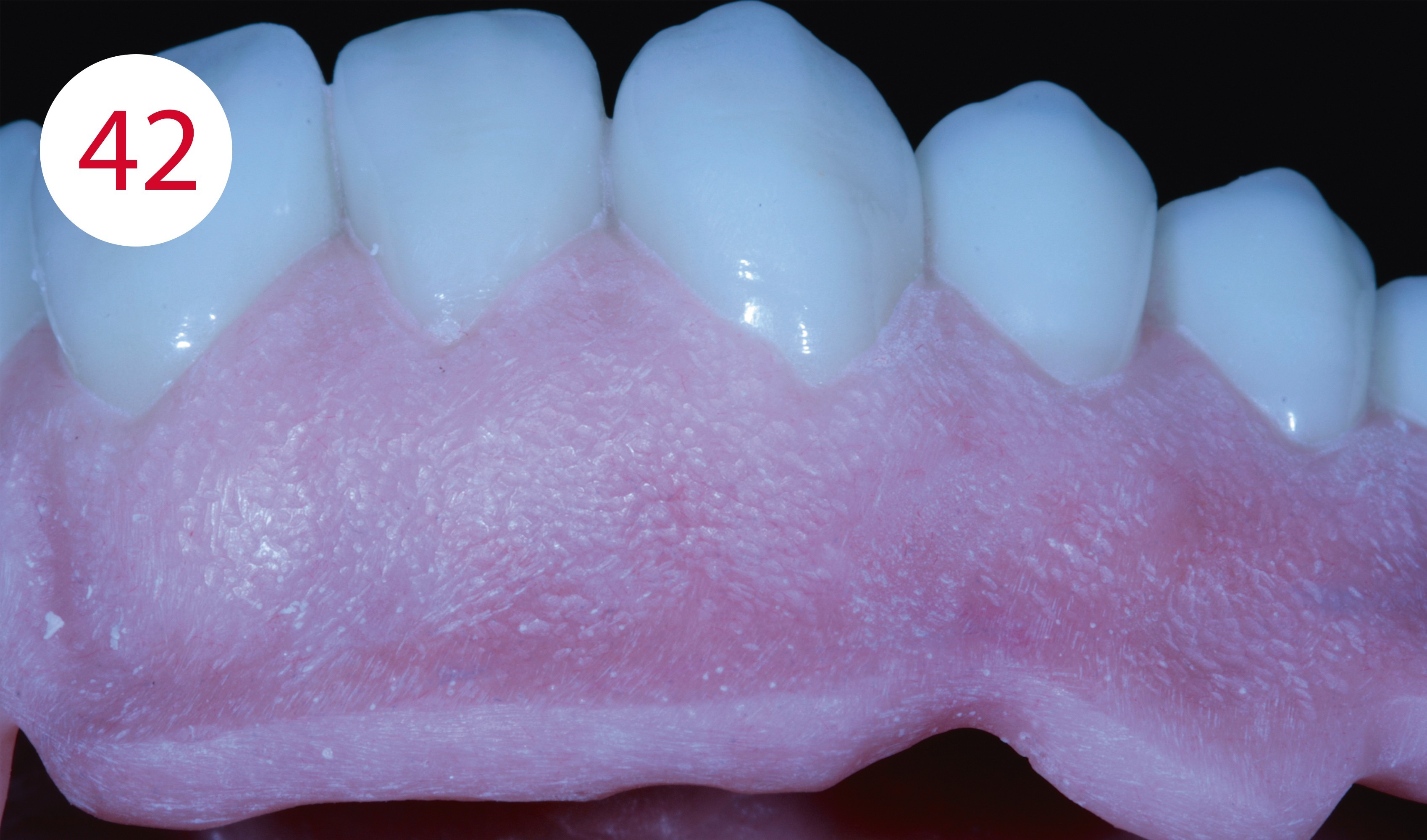
Following static and dynamic grinding of the occlusion, fine diamond grinders were used to restore the occlusal contours of the teeth from an anatomical point of view. To finish the denture bodies, these were removed from the models and machined with fine carbide cutters. First, the tongue, lip and cheek frenula were exposed so that the prostheses were not lifted under muscle activity and associated tightening (Fig. 39). The denture was then finished according to anatomical aspects using different, finely serrated cutter shapes, particularly in the area of the replicated alveolar mounds (Fig. 40). It is important here that as little grinding as possible is performed in the transition from tooth to gingiva, as this area cannot always be optimally polished without damaging the tooth surfaces. Pockets between the tooth and gingiva should also be avoided, as patients may have problems keeping these clean and food residues and concrements may accumulate. A slightly rounded smooth transition is optimal. Before the denture was polished to a high gloss, the surface was stippled with rose burs (Figs. 41, 42). Then it was pre-polished with pumice stone and various brushes and finally polished to a high gloss with polishing paste and a buff.
Fig. 39: Exposure of the frenula in their pull direction
Fig. 40: Fine-grinding of the alveolar mounds
Fig. 41 and 42: After "stippling"
MATERIALS
Articulator
Articulator CA 3.0 (CANDULOR)
Modeling wax
AESTHETIC Wax (CANDULOR)
Modeling wax for color characterization
AESTHETIC Color Wax (CANDULOR)
Isolation
Iso-K (CANDULOR)
Denture resin
AESTHETIC BLUE (CANDULOR)
Gingiva characterization
AESTHETIC Intensive Colors (CANDULOR)
Prosthetic teeth
PhysioStar NFC+ / Condyloform II NFC+ (CANDULOR)
Implant system
Comfour System (Camlog)
Alloy
NPM (Camlog/Dedicam)


Who is…?
2019
3rd place at the CANDULOR KunstZahnWerk Competition
Since October 2000
Employed in the dental laboratory Kornexl in Breitenberg
with focus on prosthetics / combination technique
1995 - 1999
Training as dental technician in Passau