
Full dentures: a complicated case solved according to the GERBER concept
Regaining chewing function, facial proportions and dento-oral esthetics
by Vittorio Capezzuto
The patient
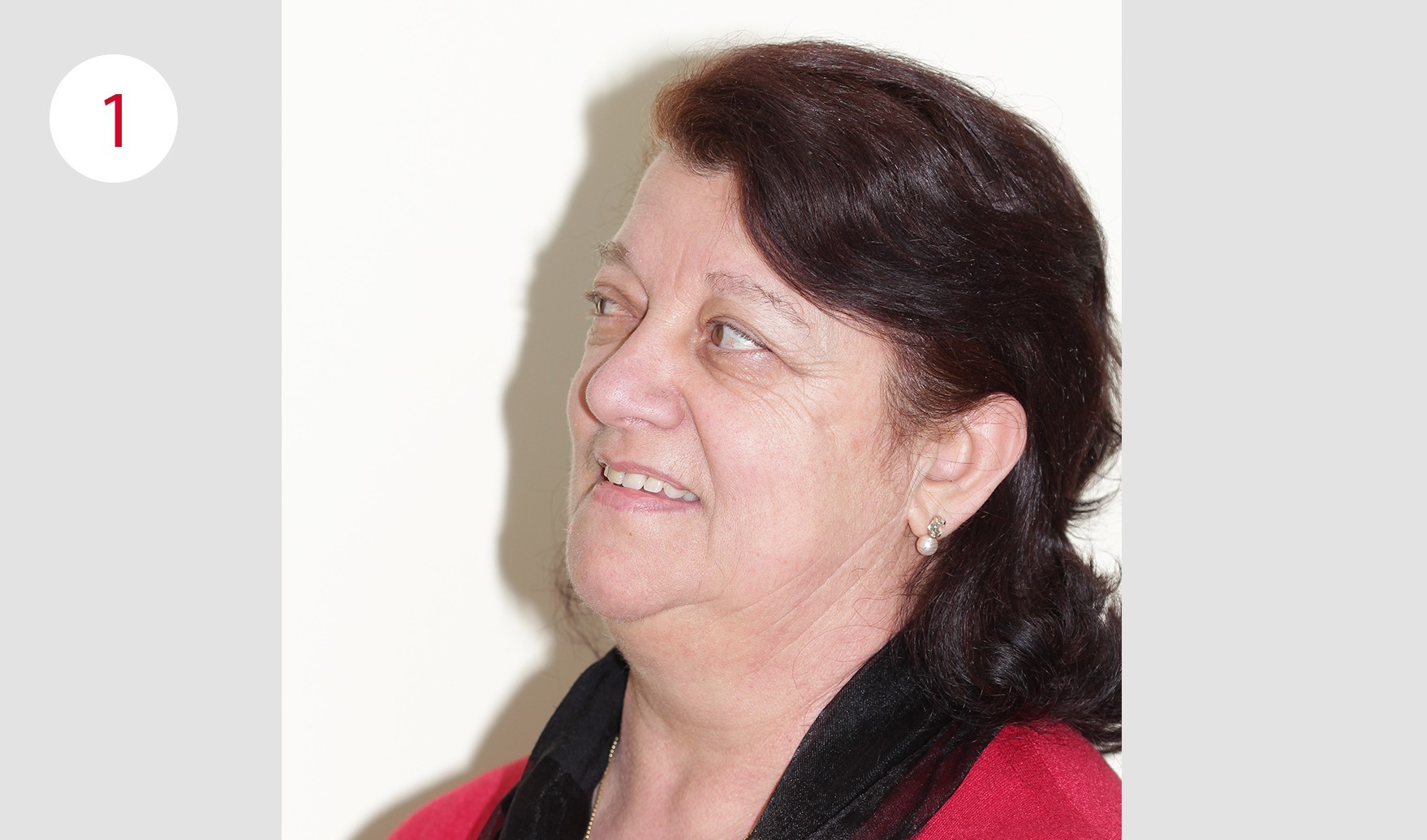
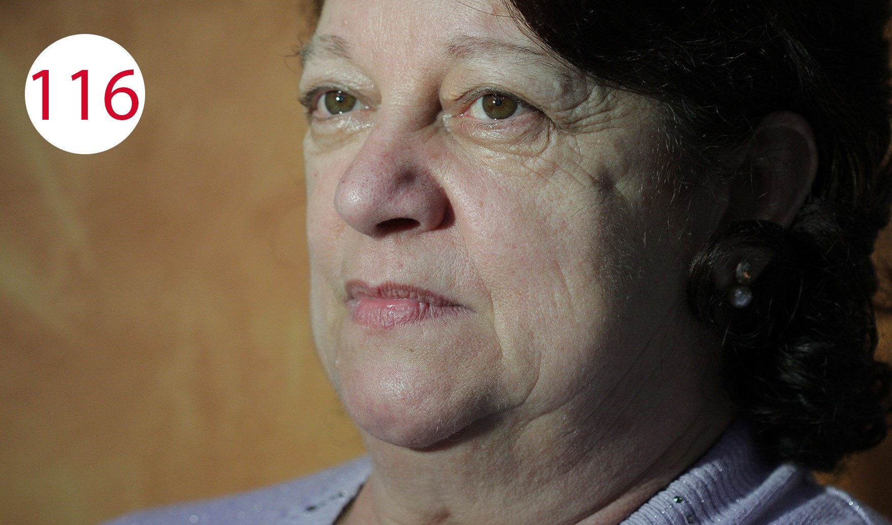
At the time of the prosthetic restoration presented here, the patient Livia was 65 years old (Fig. 1). She complained about the poor fit of her full dentures in the upper and lower jaw, in particular the pronounced movement of the lower denture caused her problems. Due to the strong mobility of the gingiva, the movement of the mandibular denture caused profound pressure points in the area of the fold with partially acute decubitus in the sublingual area. A distinct vertical loss of the lower jaw bone was determined both clinically and radiologically. For prosthetic stabilization, an implant solution with overdenture seemed appropriate and was implemented. The total maxillary denture was also be reconstructed, as the posterior teeth were severely impaired due to pronounced wear and thus caused a significant lowering of the vertical relation. To restore chewing function, a temporary immediate restoration for the upper and lower jaw, was proposed to the patient, which however, she did not agree with for personal reasons. At her request, rehabilitation was postponed until after the osseointegration of the implants had been completed.
Description of the prosthetic planning
The prosthetic planning included the adaptation of the previous dentures, the realignment of the occlusal plane as well as gingival conditioning. Then, the full dentures were fabricated using the GERBER method: a removable mucosa-supported full denture in the maxilla and an overdenture with implant-supported SEEGER bar system with passive fit in the mandible. These solutions were chosen as they can be adapted better to the objective difficulties of the situation that had to be solved. The materials used included PMMA for the denture bases, nano-filled composite teeth (NFC+), a CrCo alloy for the rigid retention part and nylon for the secondary retention.
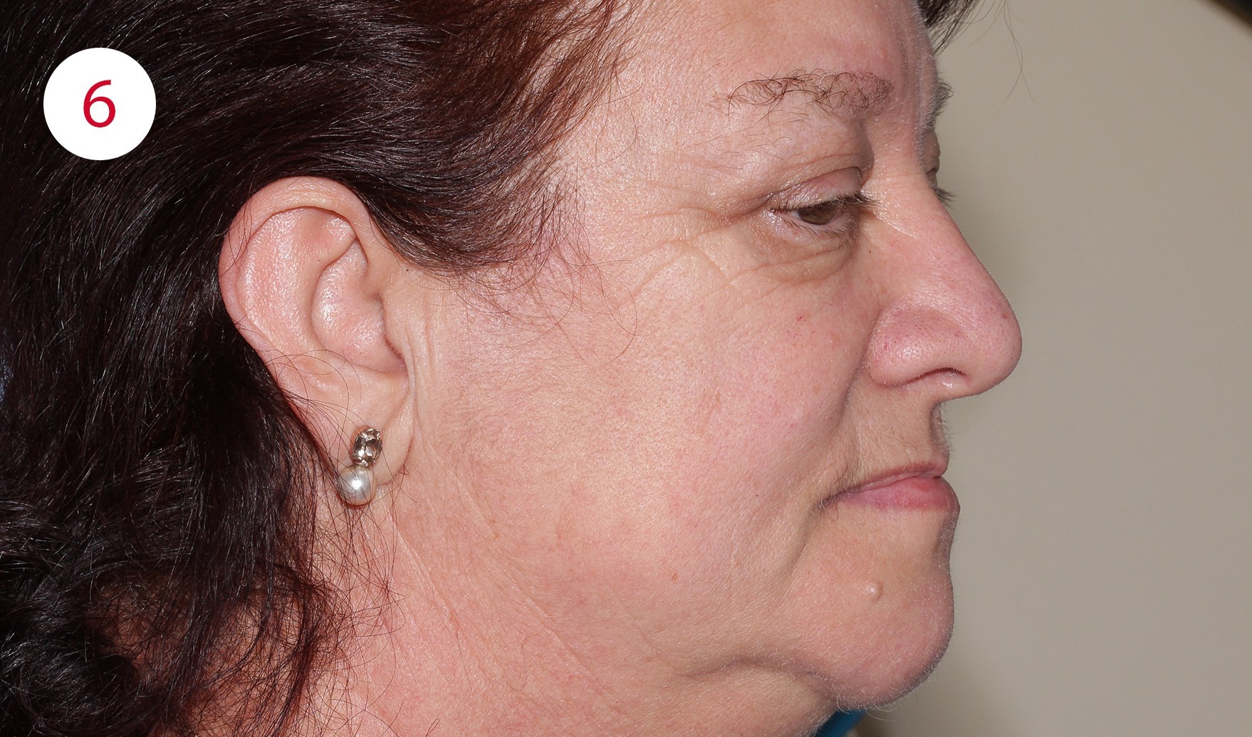
Fig. 1: Photo of the patient before

Case description
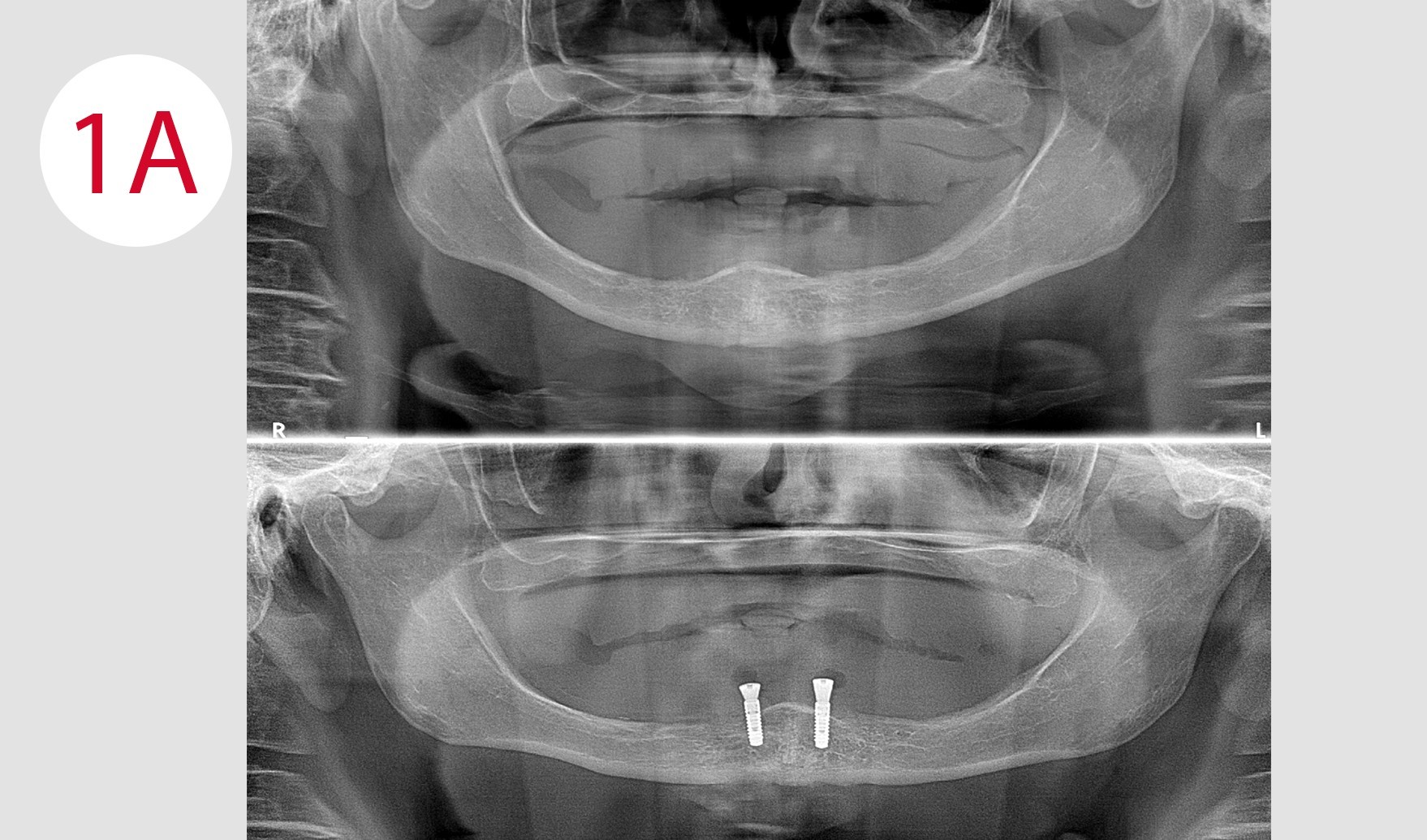
Following the mandatory preliminary examinations, two implants were placed according to the BRANEMARK method in the chin area, as the volume of the bone permitted this and there were no risks of burdening the arteriovenous structures (Fig. 1A). After allowing an appropriate period of time for osseointegration, prosthetic rehabilitation of both jaws was performed. The objective local examination showed a reduction of the jawbone in the anterior region in vertical direction, which was clearly due to insufficient planning of the occlusal plane and thus attributable to an insufficient distribution of the chewing force, which is symptomatic for the KELLY syndrome.
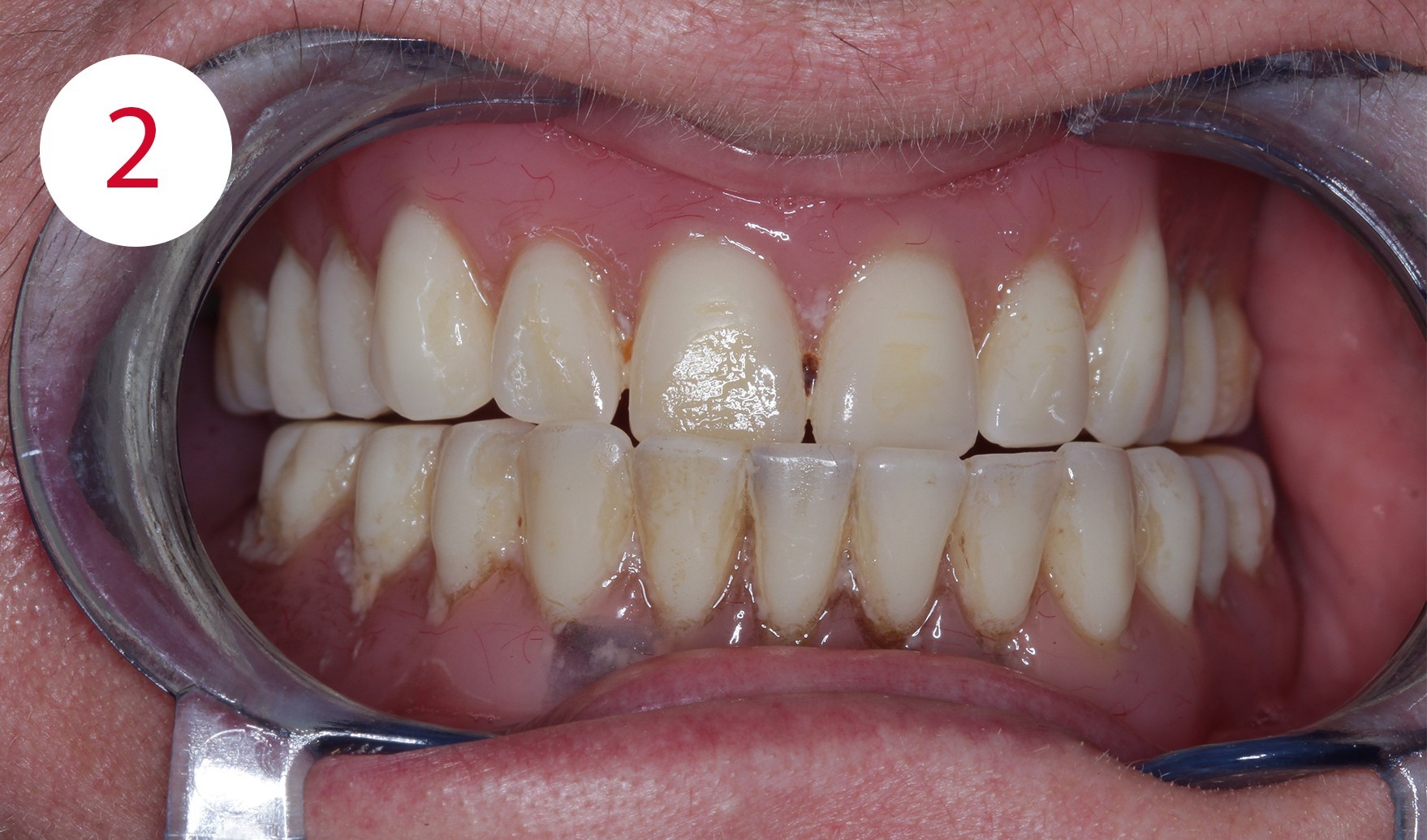
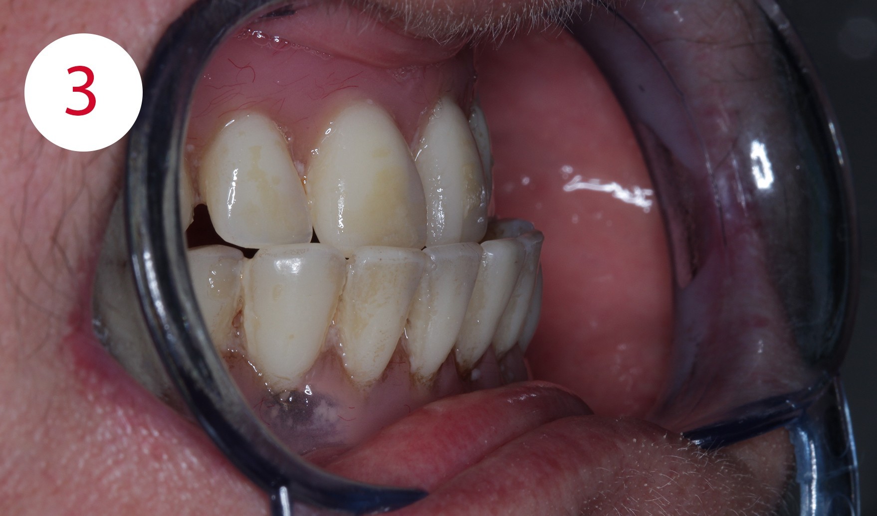
In addition, a loss of vertical dimension due to wear of the existing artificial teeth was detected during the clinical examination; the purely physiognomic examination revealed a "senile-looking" relation between the upper and lower face (Figs. 2, 3, 4, 6).
Restoring the vertical relationship
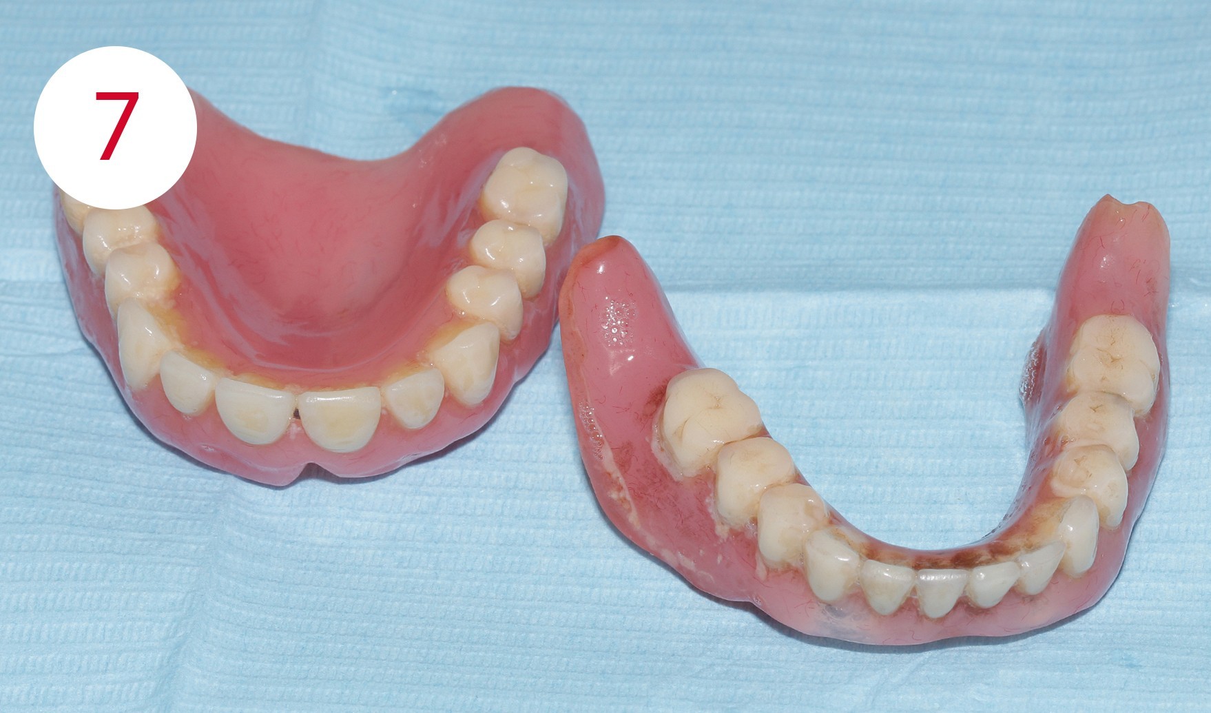
For the new restoration, the previous dentures were used, as they could easily be used as aids for planning the new dentures (Fig. 7). They were used to reconstruct the vertical relationship.
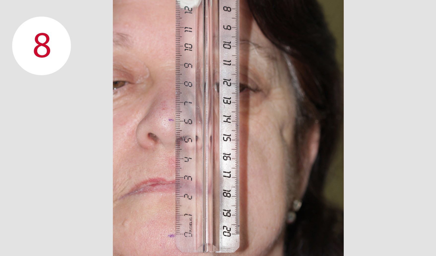
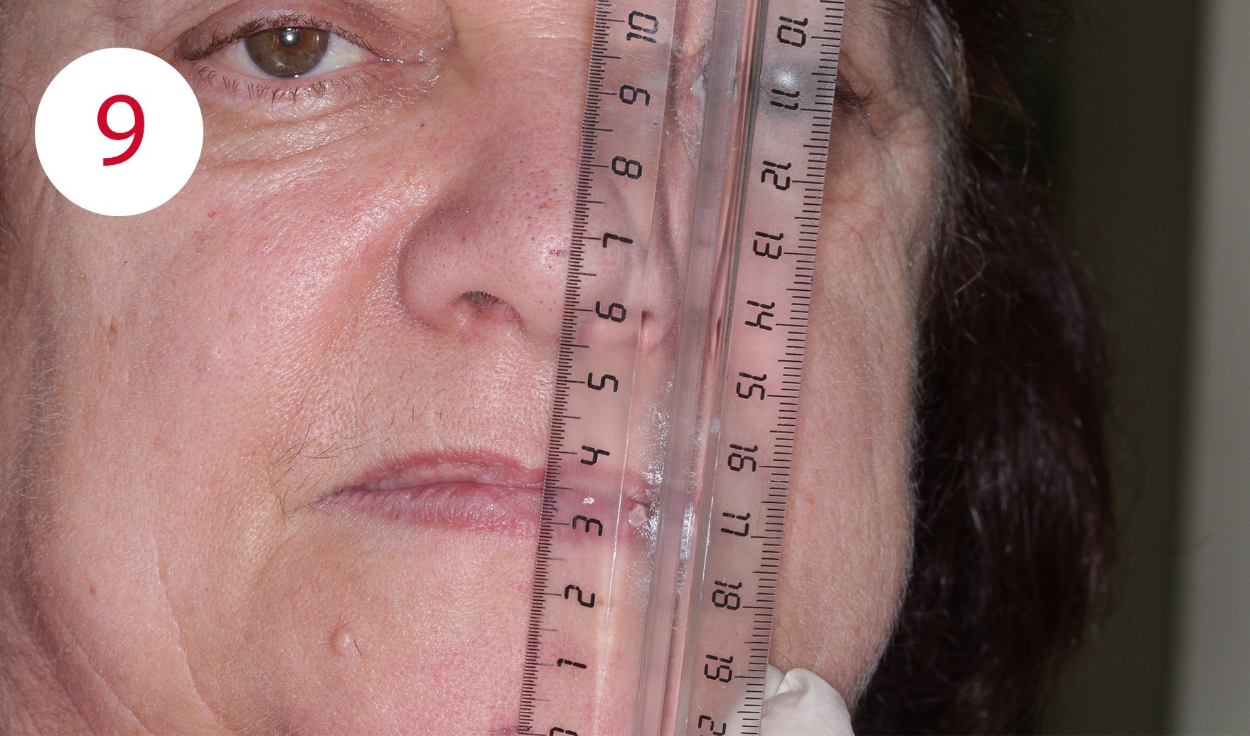
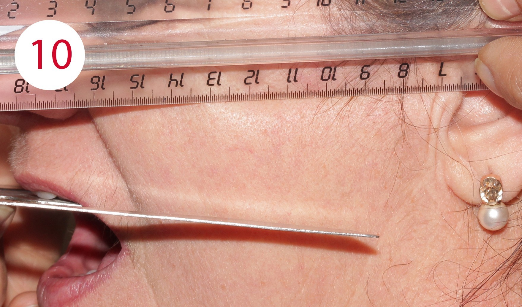
For this purpose, two reference points were marked for distance measurement during the resting position, which is usually two to four mm from the occlusal contact point of the habitual intercuspidation position (Figs. 8, 9). During the examination for the reconstruction of the occlusal plane, it became obvious that the current dentures were clearly aligned disparallel to the Camper's plane. This is defined bilaterally at the head and runs from the deepest point of the nasal wing to the tragus center in the anterolateral part of the outer ear (Fig. 10). Although these parameters deviate slightly from the reference points defined on the skull, in daily practice this deviation has proven to be a negligible variance in the sagittal direction of occlusion for both mucosa-supported full dentures as well as implant-supported overdenture restorations. The parallelism between Camper's plane and the occlusion plane has an average distance of approx. 34 mm. A bite fork and an occlusionome resp. was used to determine and check parallelism. This aid illustrates the inclination of the plane outside the mouth where the subsequent dentures will occlude.

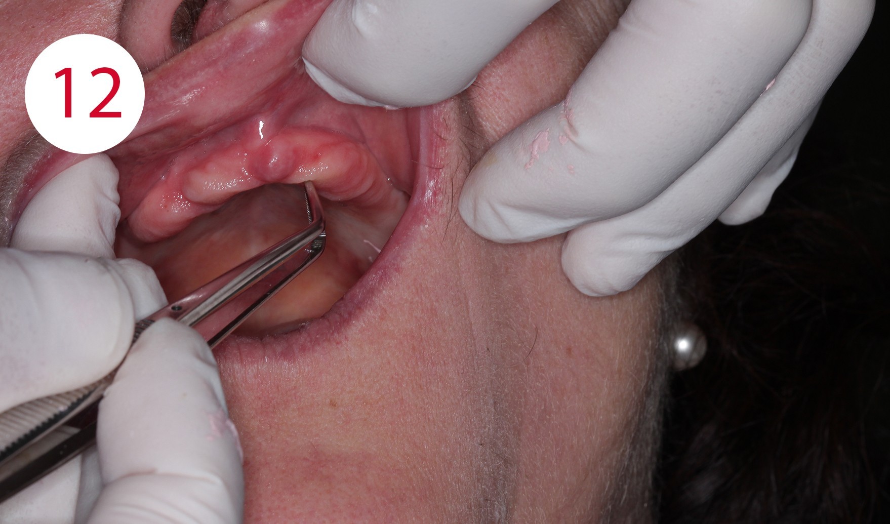
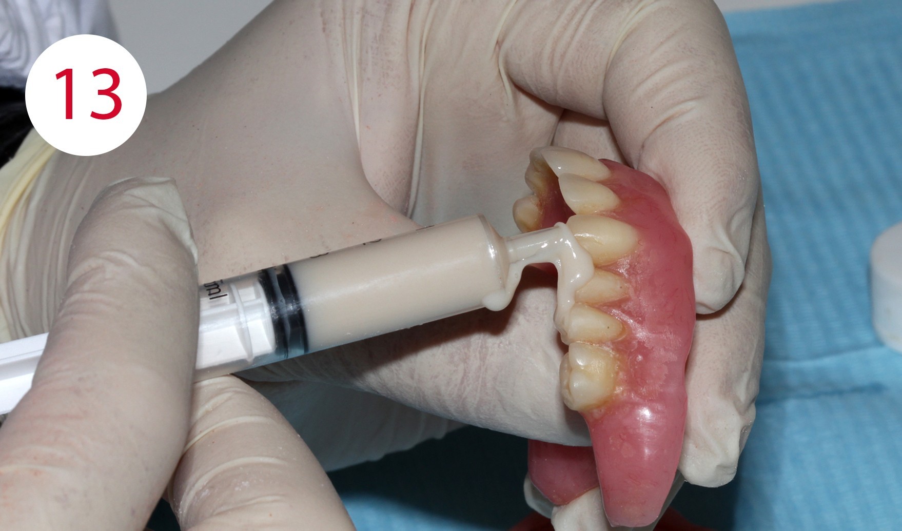

When the maxillary denture is inserted, the disparallelism of both planes can be seen clearly for the present case. The occlusal plane extends downwards to the rear and not parallel to the Camper's plane, i.e. to the front and slightly ventrally. The present progression is responsible for the formation of pressure sores and ulcers which, as in this case, led to long-term bone atrophy and caused a KELLY syndrome. Using surgical forceps, the associated mobility of the mucous membrane could be demonstrated in the patient (Figs. 11, 12). As a consequence, the first step was to create parallelism between the Camper's plane and occlusal plane by applying cold-curing resin for temporary crowns and bridges. Beforehand, the respective surfaces of the existing artificial teeth were cleaned and provided with retentions (Fig. 13). The posterior part of the prosthesis was adapted to the Camper's plane similar in manner to a splint preparation with posterior alignment (Fig. 14). In this phase, the incisal edges of the upper anterior teeth were extended appropriately as they were too short, both phonetically and esthetically. To improve parameterization of the increase of the vertical dimension in this phase, reference was made to photos of the patient taken at a young age before the onset of the morpho-functional decay of the two jaws.
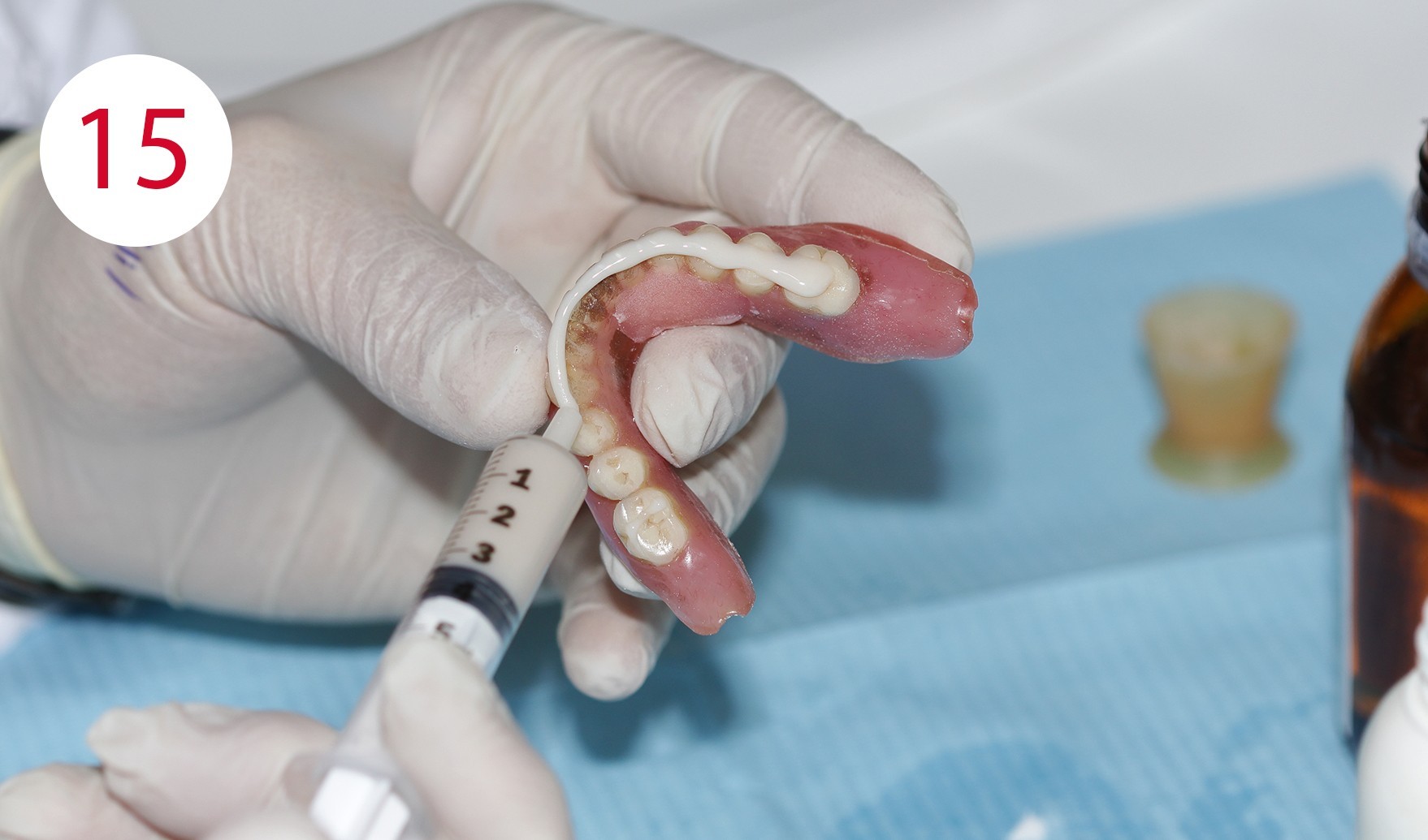
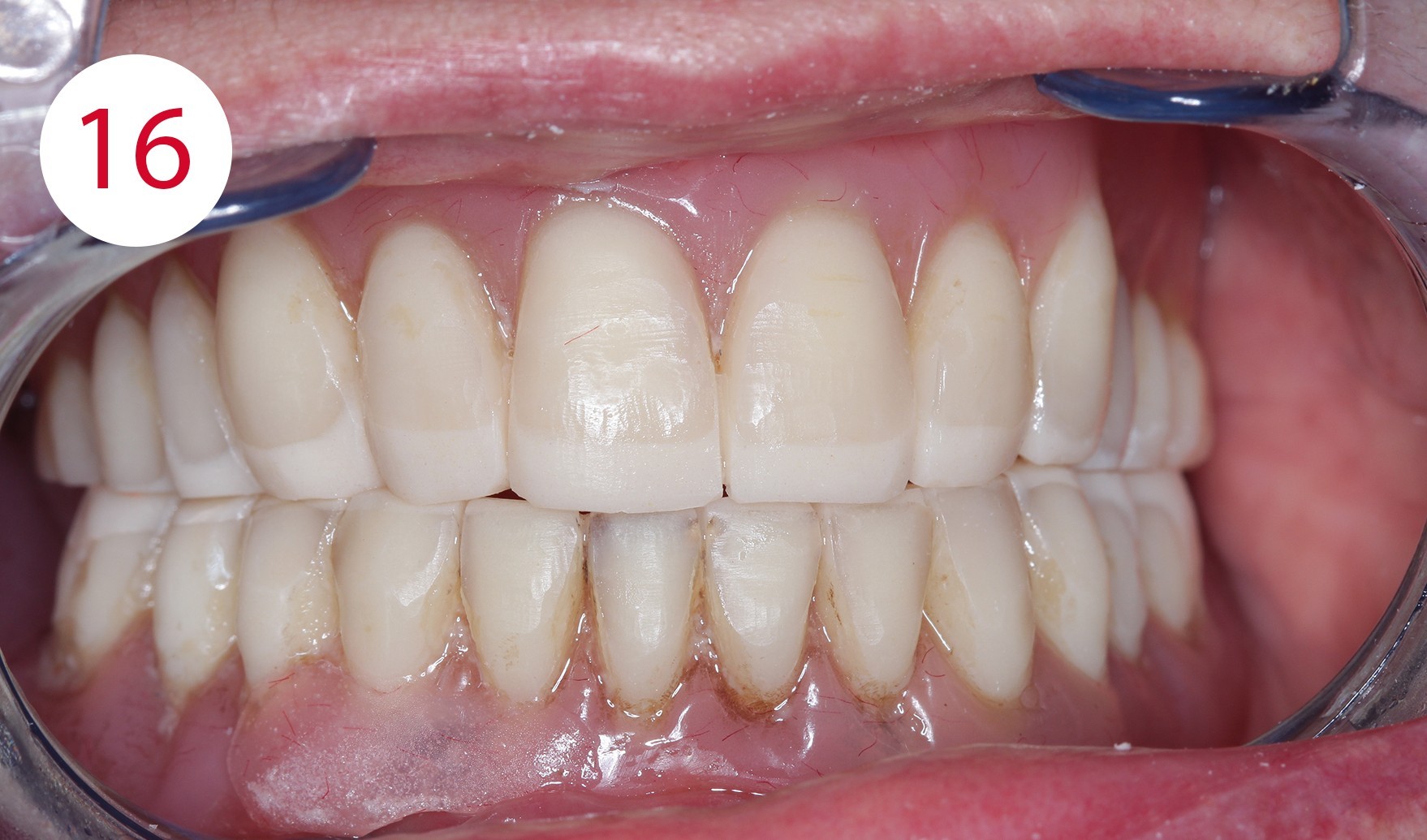
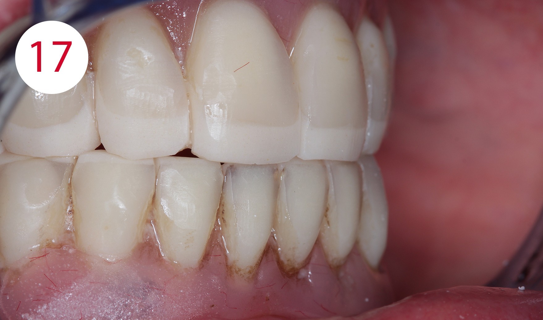
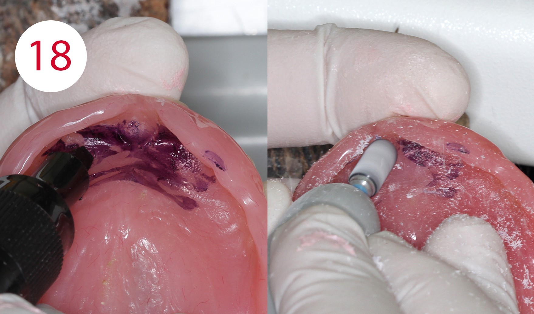
After completion and polishing of the vertically corrected maxillary prosthesis, the lower prosthesis was adapted in the same manner (Fig. 15), as the selected resting position as a reference deviated significantly more than two millimeters from the occlusal position. After correct empirical and functional values of the vertical dimension had been restored, upper mucosal conditioning was started, which required a long-term functional impression. To this end, FITT (KERR) was used and the denture was worn for approx. four weeks (Figs. 16, 17, 18, 19). The maxillary prosthesis was significantly relieved and emptied in the premaxillary region, where the fibro-mucosal tissue was affected extensively by the development of the KELLY syndrome.
Due to the previous measures, it was also possible to avoid any further stress on this region, which had already been subjected to excessive stress for some time on the antero-posterior, supero-inferior and latero-lateral axes.
Figs. 16 and 17: Dentures after adaptation to the Camper's plane
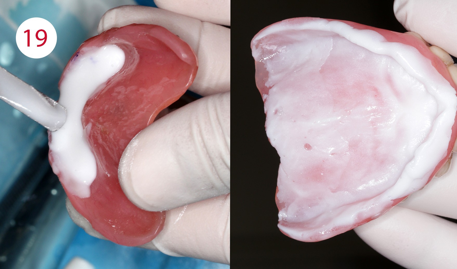
Long-term relining
The relining material was applied and used in a thin flowing consistency. Satisfactory results were observed after approximately one month and at least four clinical examinations, i.e. a significantly increased prosthetic stability, the absence of irritative noxae to the detriment of the mucous membrane as well as a functional impression in the form of the maxillary denture used, which in addition exhibited a therapeutically useful interocclusal position.
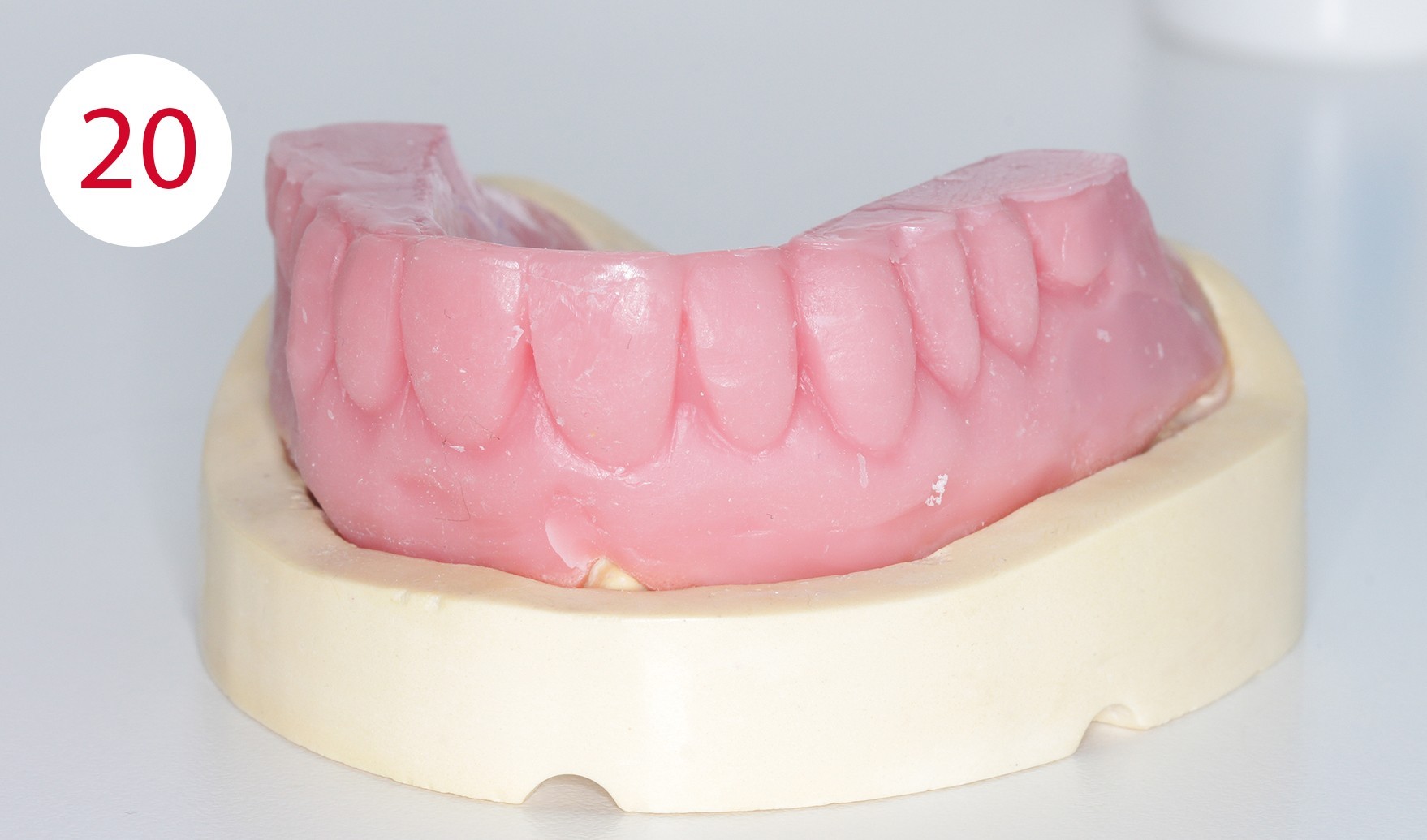

Fabrication of templates
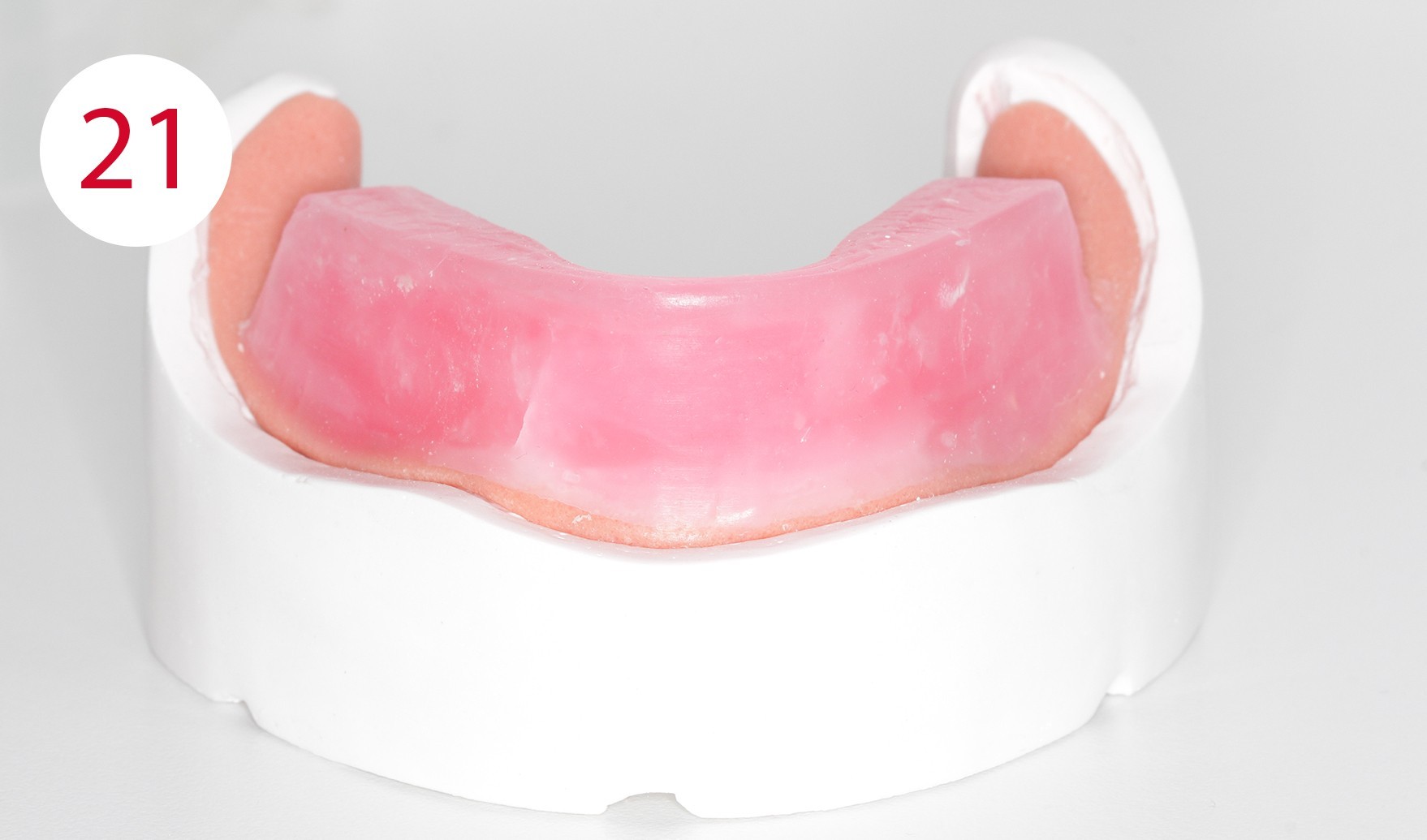
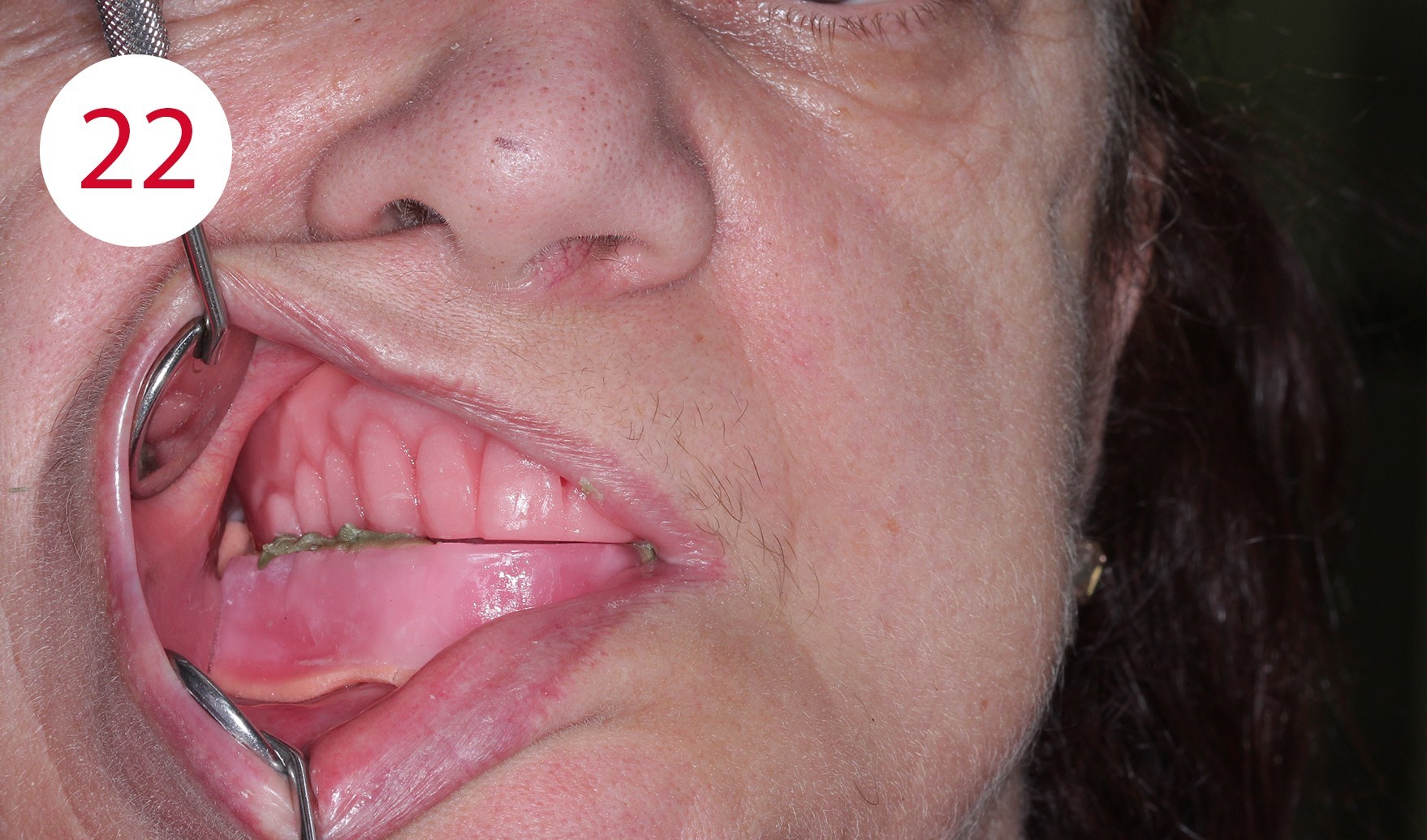
The functional model was fabricated from synthetic super hard plaster type IV as well as vestibular and lingual silicone masks (Fig. 20). After fabrication of the denture base from cold-curing polymer, the silicone masks were filled with AESTHETIC WAX HARD (CANDULOR). Due to the implants, an impression was taken in the traditional way for the lower model. The bite template was fabricated on the functional model (Fig. 21). In the following clinical visit, the jaw relationship was determined and only in a horizontal plane, as all other references such as the occlusal plane, midline, canine tooth line and smile line were already determined accordingly and correctly beforehand within the context of determining the vertical dimension with the aid of the currently worn dentures (Figs. 22, 23).
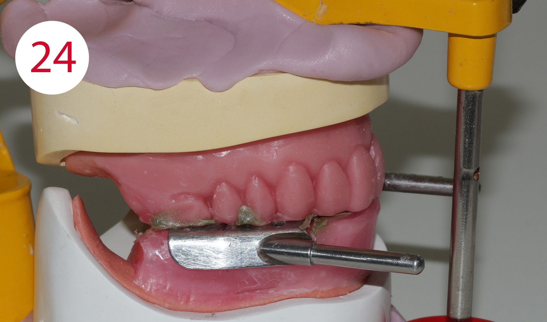
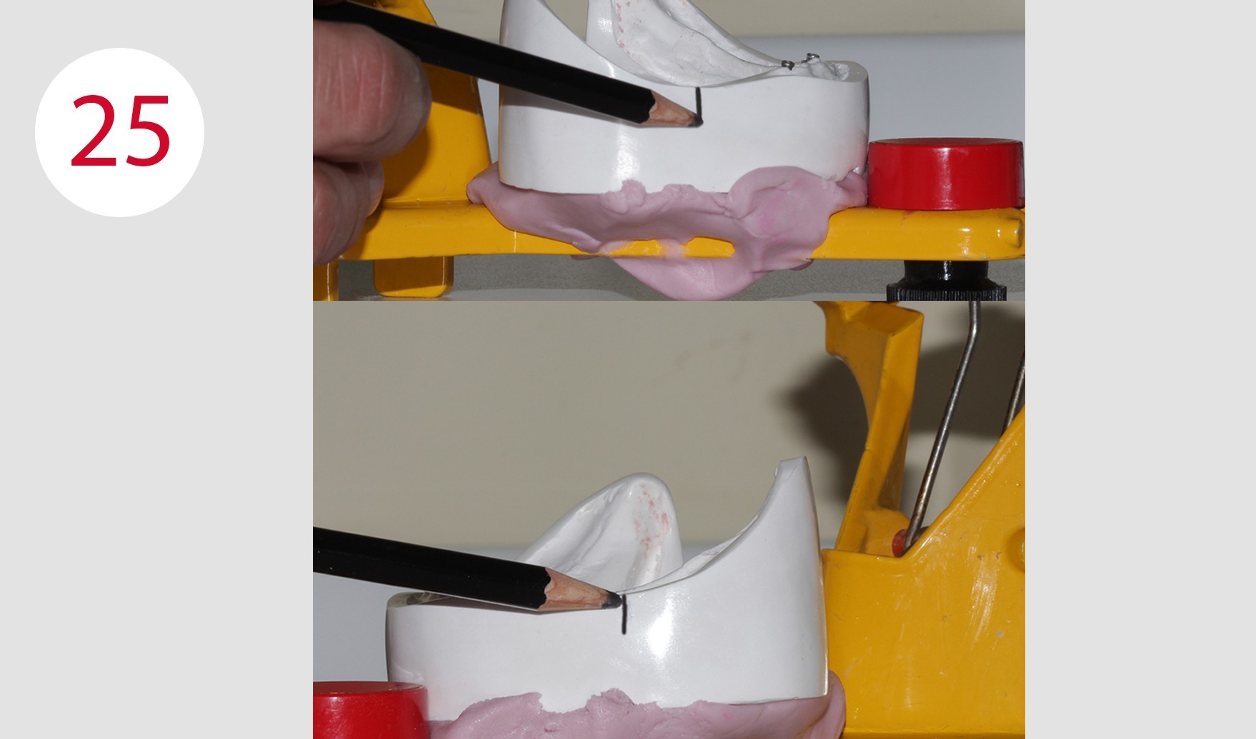
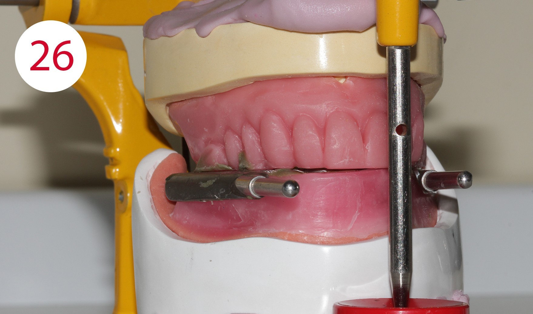
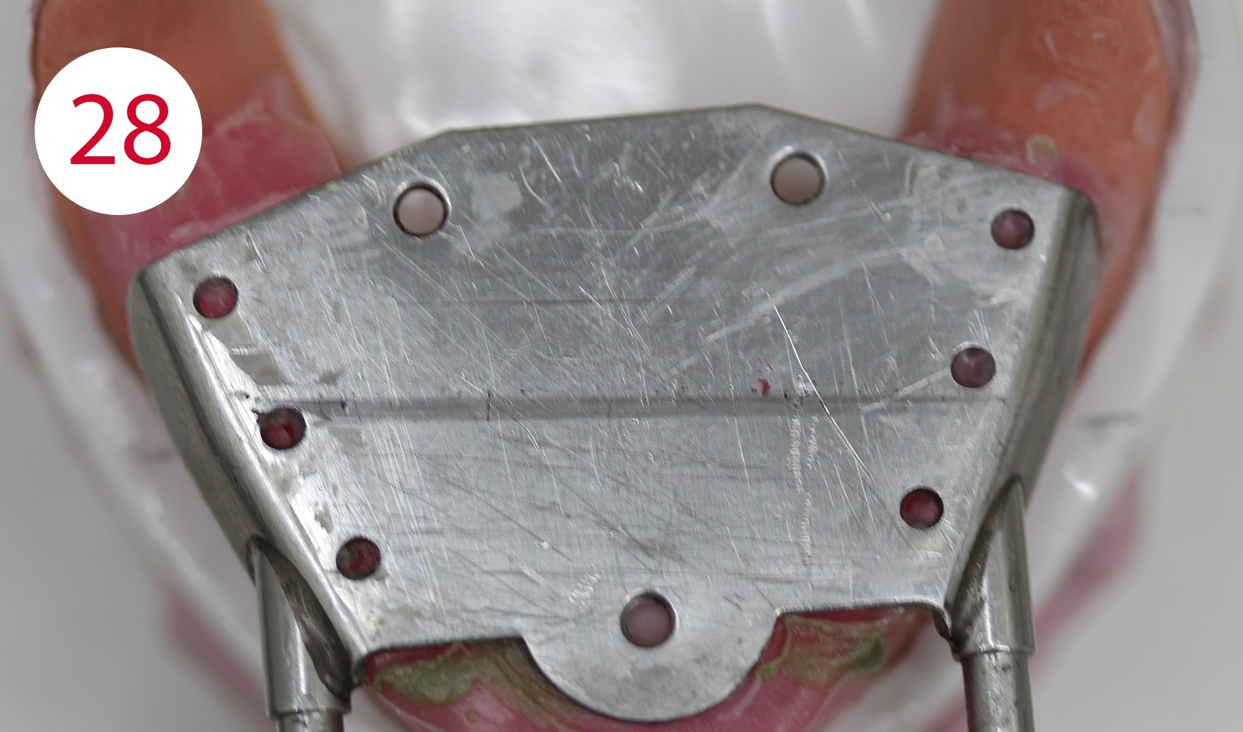
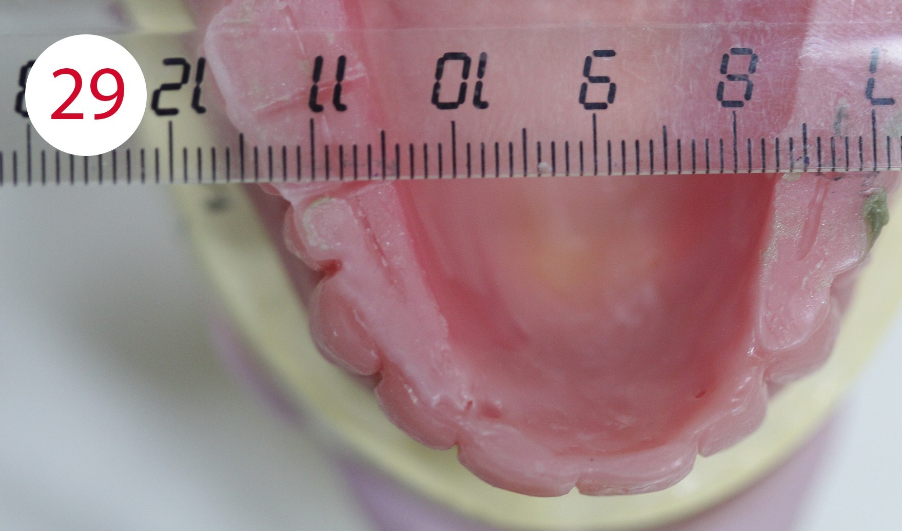
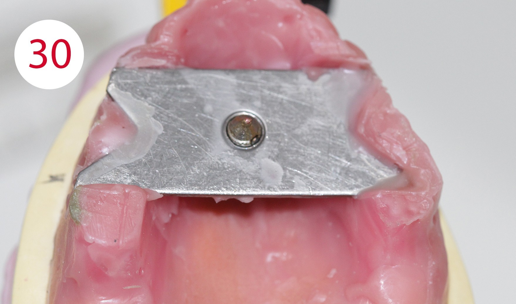
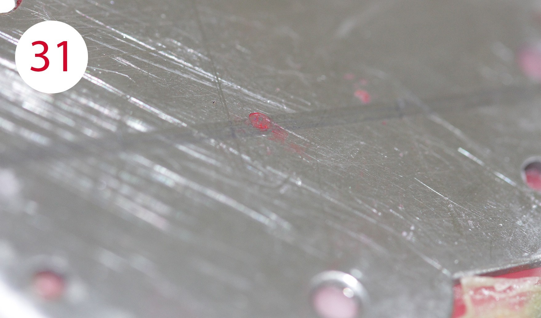
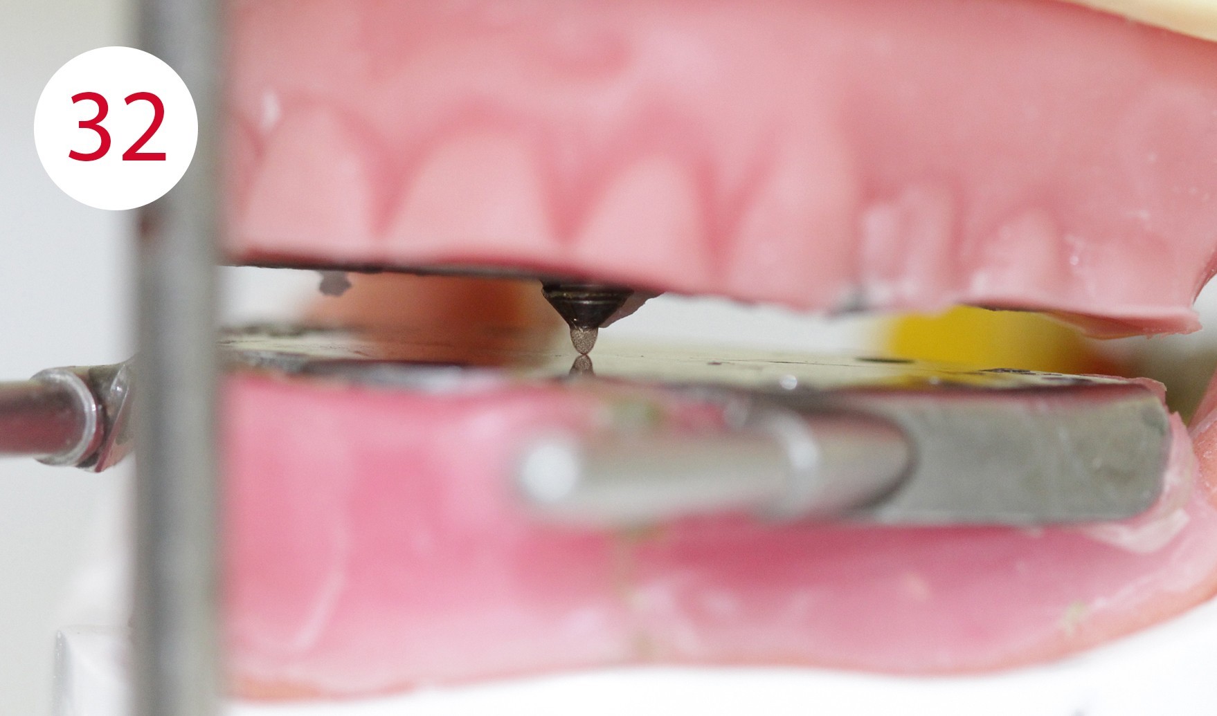
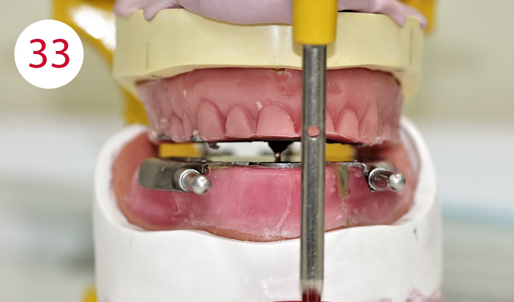
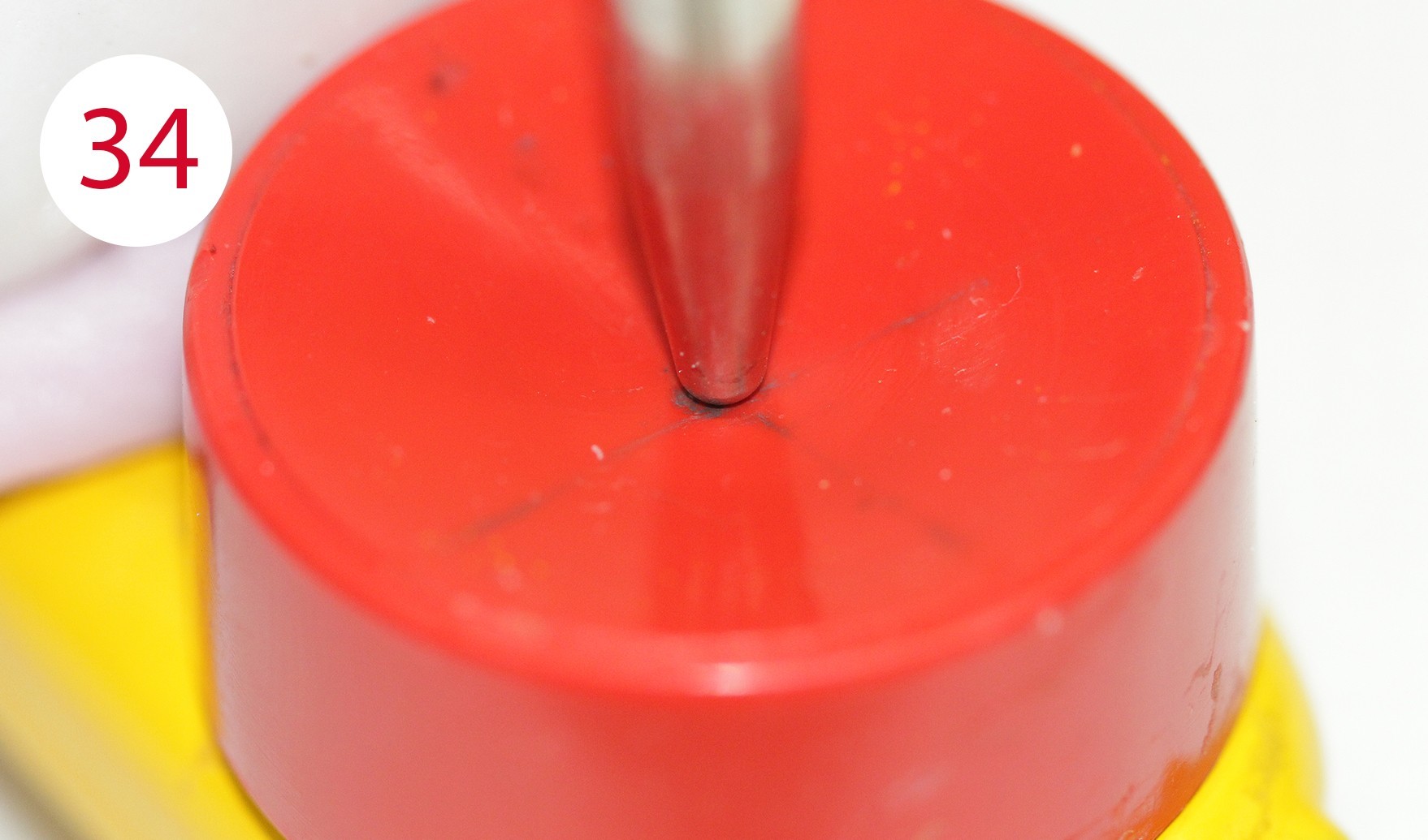
The functional models were oriented at average values in the articulator using a dimensionally stable kneading silicone to be able to fabricate the templates for intraoral support pin registration, which were to be used to record the Gothic arch and to retain the set vertical dimension unchanged for this preparation (Fig. 24). To stabilize the registration pin against vertical forces during registration, the lowest point of the ridge is determined on both sides of the mandibular model and marked on the outer surface of the model (Fig. 25). The writing plate is mounted in the lower jaw by heating the wax there and pressing it in slightly. Vertical reference is the zero position of the articulator support pin with the upper and lower wax walls lying parallel to each other. Here it must be ensured that both wax walls are harmonized. Then the upper butterfly-shaped plate is mounted to accommodate the registration pin. For this purpose, the metallic registration pin is slightly screwed back so that the tip of the registration pin protrudes, so that its position can already be checked during assembly by the contact point on the lower writing plate. The plate is also heated for this purpose and carefully pressed onto the upper bite rim. Ideally, the verification contact should be on the line connecting the two lowest points of the lower lateral ridge (Figs. 26, 28, 29, 30, 31). To allow undisturbed and visually controllable lateral and protrusion movements in the mouth, the upper bite rim is now cut back without changing the vertical dimension of the occlusion (Figs. 32, 33, 34).

Support pin registration
In preparation for intraoral support pin registration, the hinge axis points and the outer wall of the joint cusps are determined on the patient so that the facial bow can be anatomically aligned, the sagittal inclination of the joint can be correctly recorded, and correspondence between the hinge axis of the facial bow and that of the articulator can be ensured. For this purpose, two methods have become established to determine the condylar hinge axis at the head: one is statistical and one is palpatory.
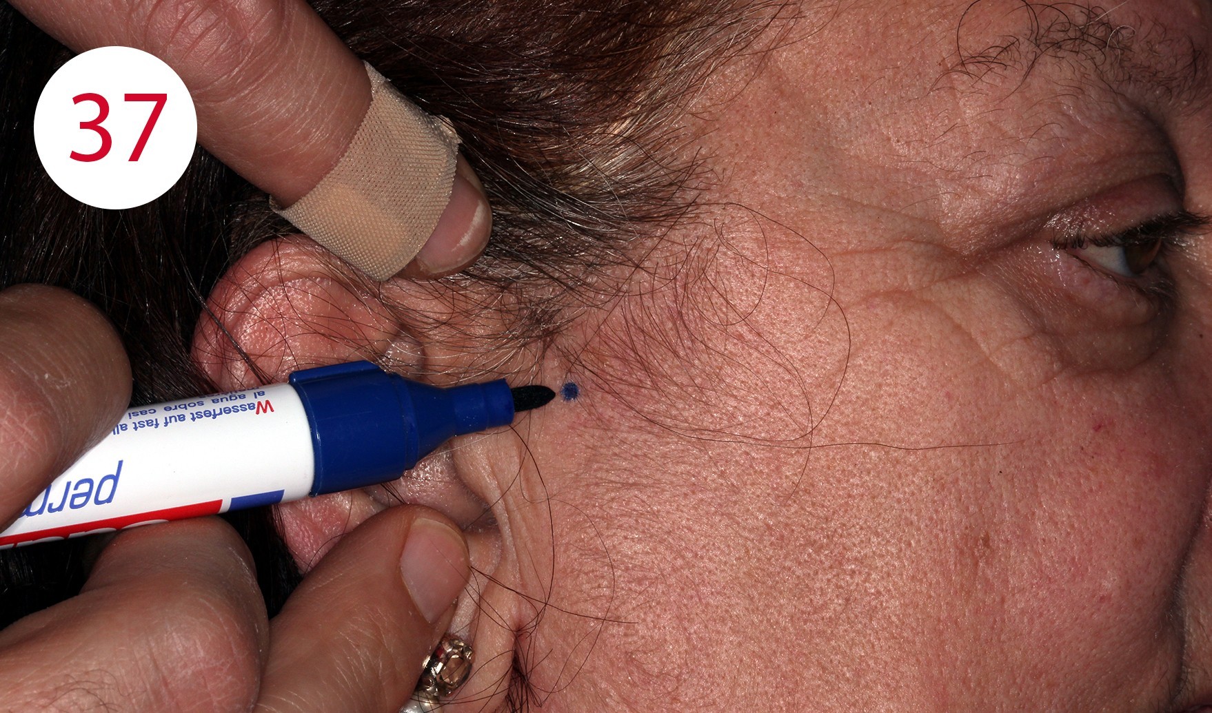
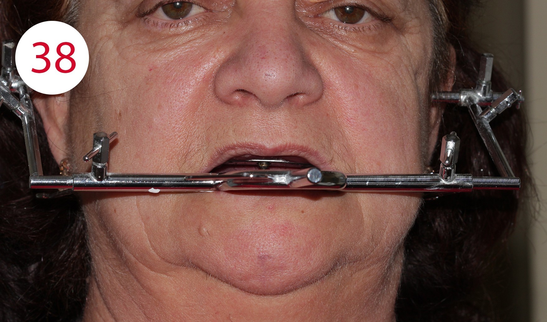
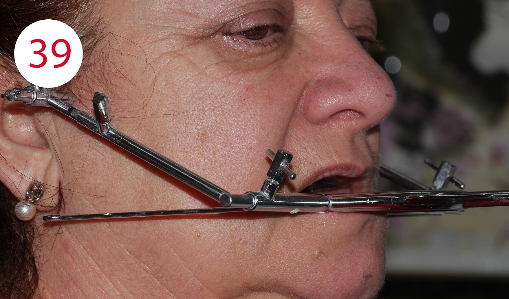
The statistical version states that the condylar hinge axis is located about 13 mm from the line between the temporal eyelid angle and the tragus. For the palpatory method, which we applied here, the patient is asked to perform small mandibular movements to be able to feel the position of the condyle with the small finger in the area of the joint cusp in front of the tragus (Figs. 36, 37). The DYNAMIC FACEBOW according to GERBER (GERBER CONDYLATOR) was used as a face bow with recording of the sagittal joint inclination. This is a kinematic facebow whose correct position is determined by the patient assuming (maximum) retrusion without effort to match the tips with the writing leads with the reference points marked on the skin. Here it is best to follow the "clockwise rule" to check the identification of the hinge axis (Figs. 38, 39).
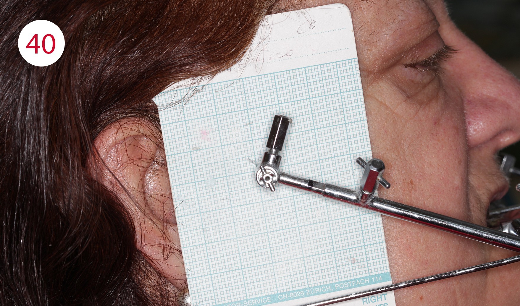
Sagittal joint path measurement
To record the sagittal joint inclination, the registration cards (Fig. 40) are inserted between the writing lead and the skin so that the lines are parallel to the reference rod of the facial arch (occlusal plane indicator) and thus parallel to the occlusal plane. The patient treated here was asked to perform protrusion movements with her mouth closed. This procedure is repeated three times as a matter of principle to determine the mean value of the sagittal joint path inclination. Here, the so-called "functional" part of the recording is of importance, which corresponds to the probable sliding of the condyles on the joint cusp (tuberculum articulare).
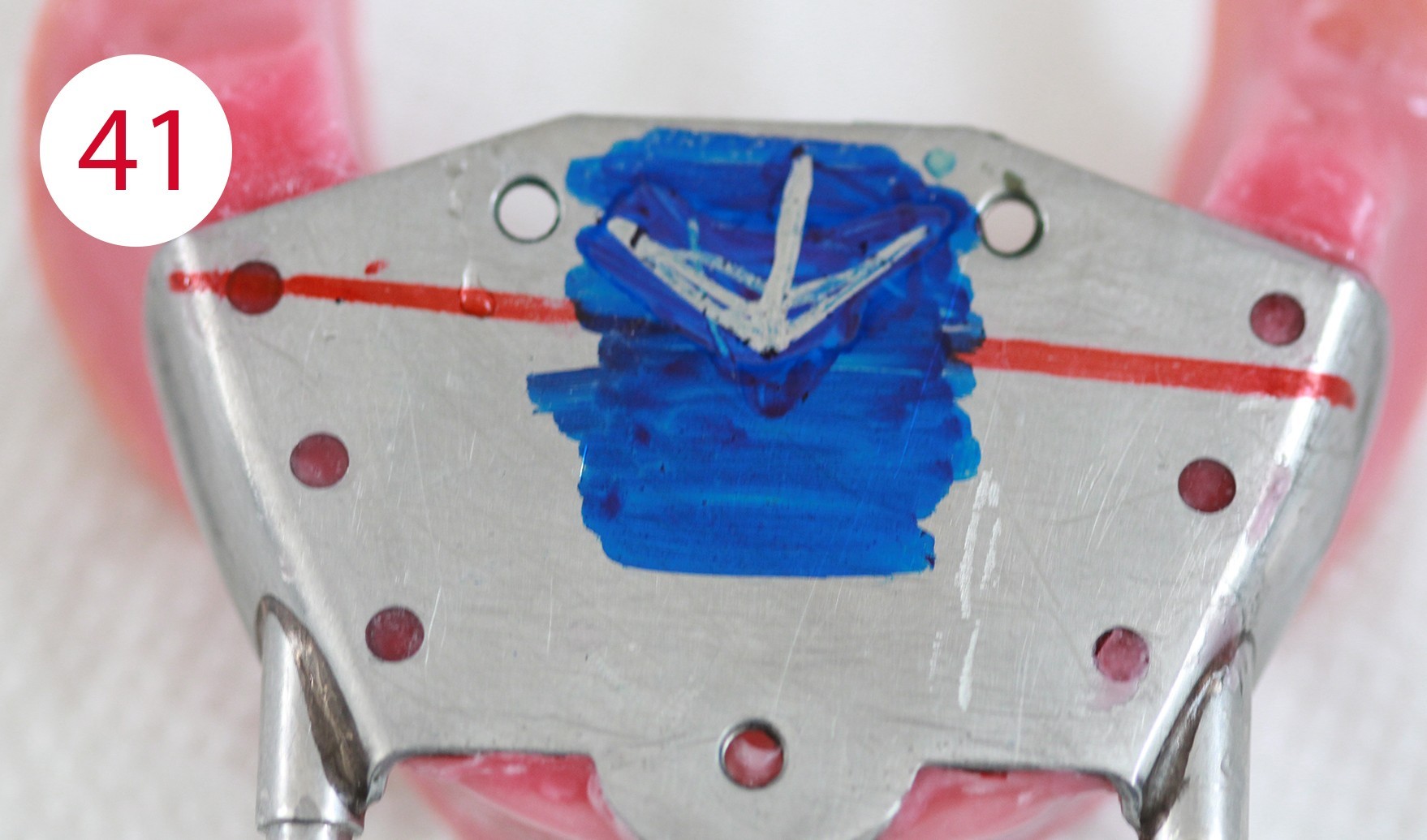
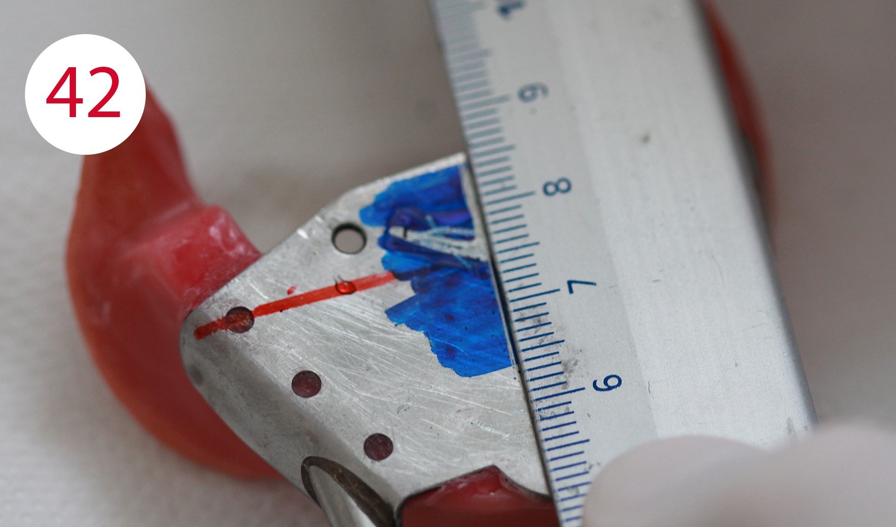
Intraoral support pin registration
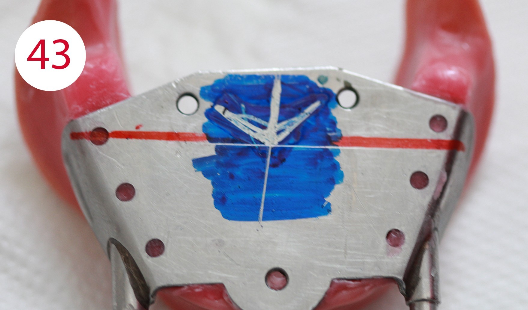
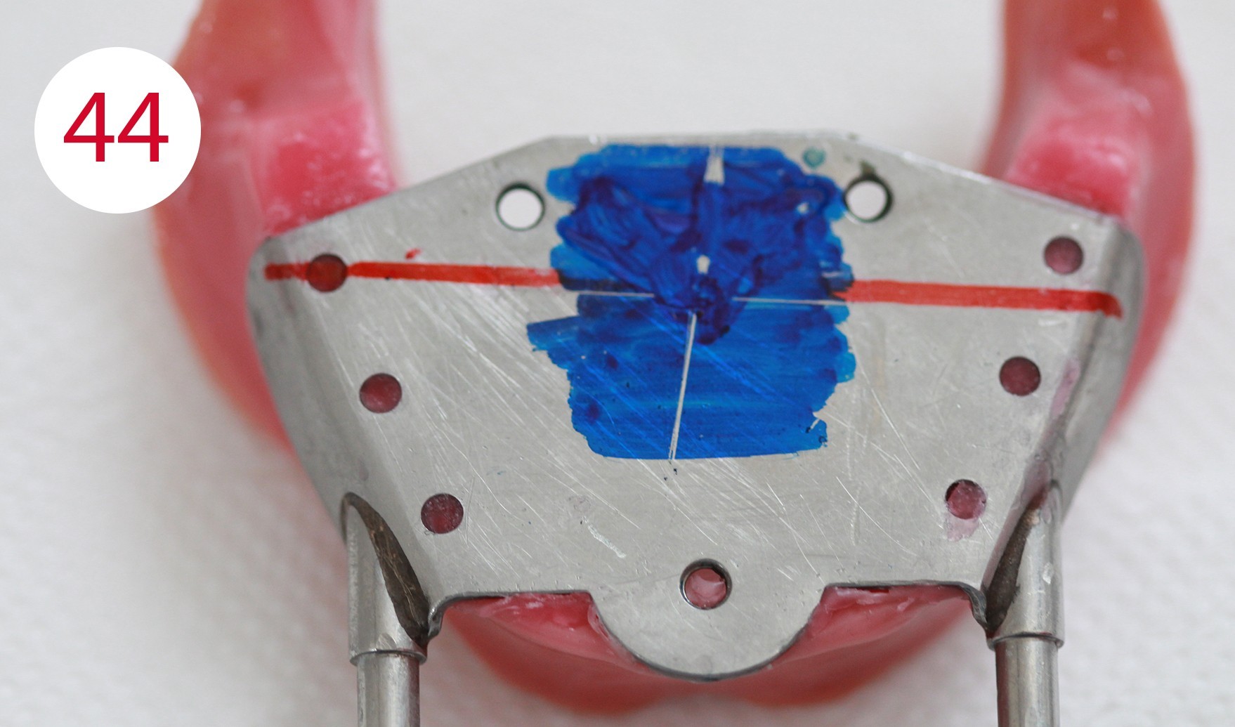
This was followed by the intraoral registration of the supporting pin, which was recorded in the horizontal plane (Fig. 41). It is used to determine the horizontal position (sagittal and transversal) of the mandible to the maxilla as "therapeutic" position (Figs. 42, 43). The position is found by comparing the neuromuscularly determined centric with the vertex of the Gothic arch. Before, the writing plate (lower jaw) is dyed and the patient, like our patient here, is asked to perform eccentric movements - protrusion, laterotrusion to the left and right. The movements mentioned above draw the so-called Gothic arch through the supporting pin (in the upper jaw) onto the writing plate positioned in the lower jaw. The lower registration template is removed and two lines are drawn on it: the protrusion line and the transversal to the arrowhead. This makes it possible to identify the vertex again and to compare it with the neuromuscular centric. To do this, the surface of the Gothic arch is again dyed before being re-inserted into the mouth. Accordingly, the patient was then asked to perform small opening and closing movements in rapid succession to determine her neuromuscular closing point.
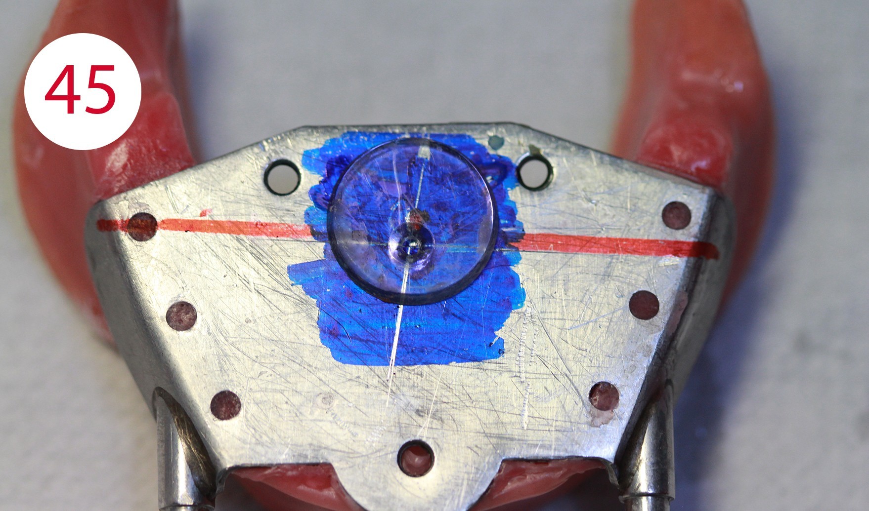
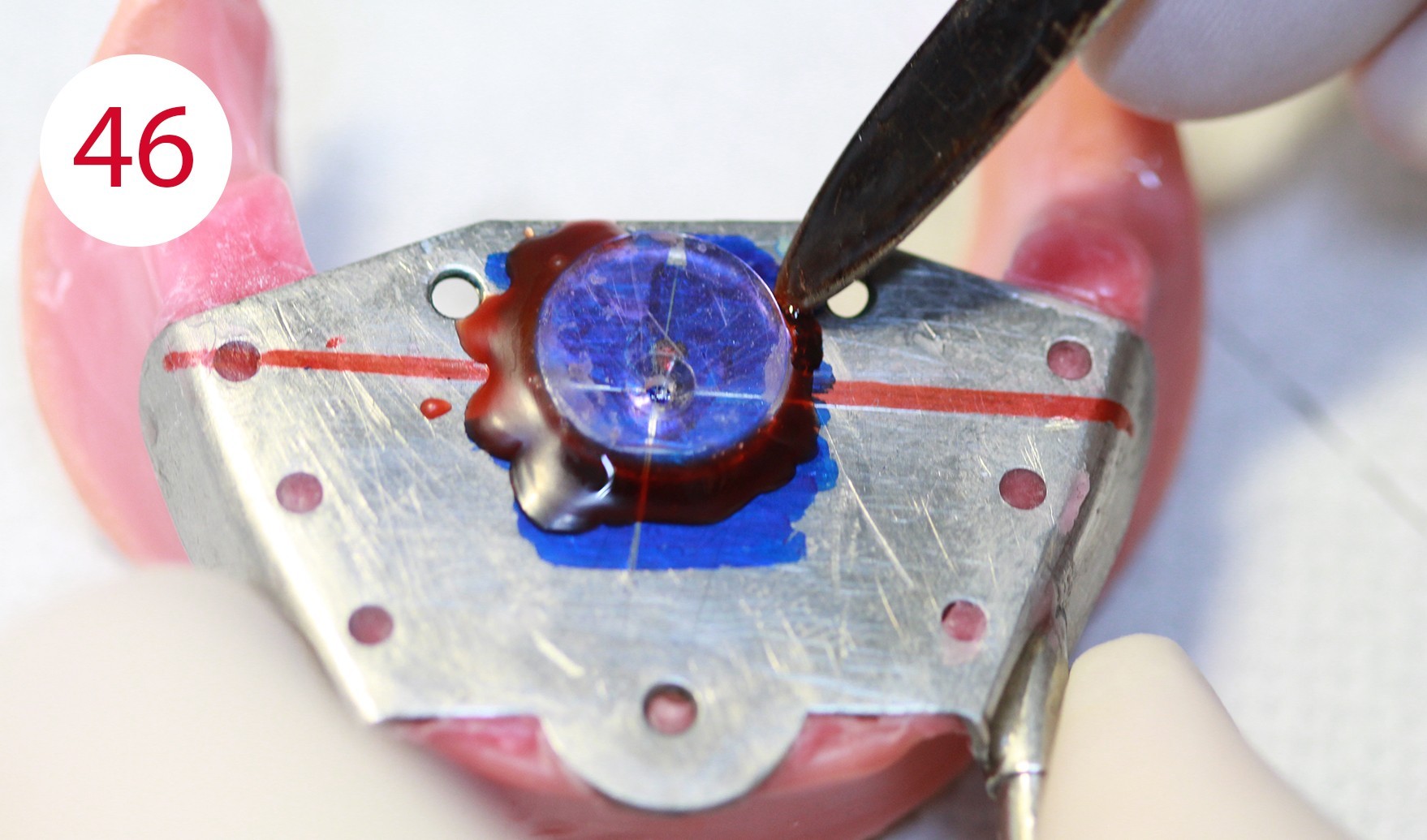
The neuromuscular centric is normally 0.5-1.0 mm before (anterior) the vertex of the Gothic arch (Fig. 44). If the vertex of the Gothic arch and the neuromuscular centric, as is the case in this patient, are not more than 0.5 mm apart, a Plexiglas disc is fixed to the vertex of the Gothic arch (Figs. 45, 46). If the distance is greater than 0.5 mm, an intermediate position is determined which is referred to as "therapeutic" and lies between the vertex of the Gothic arch and the neuromuscular centric. However, this position must be perceived as being comfortable by the patient.
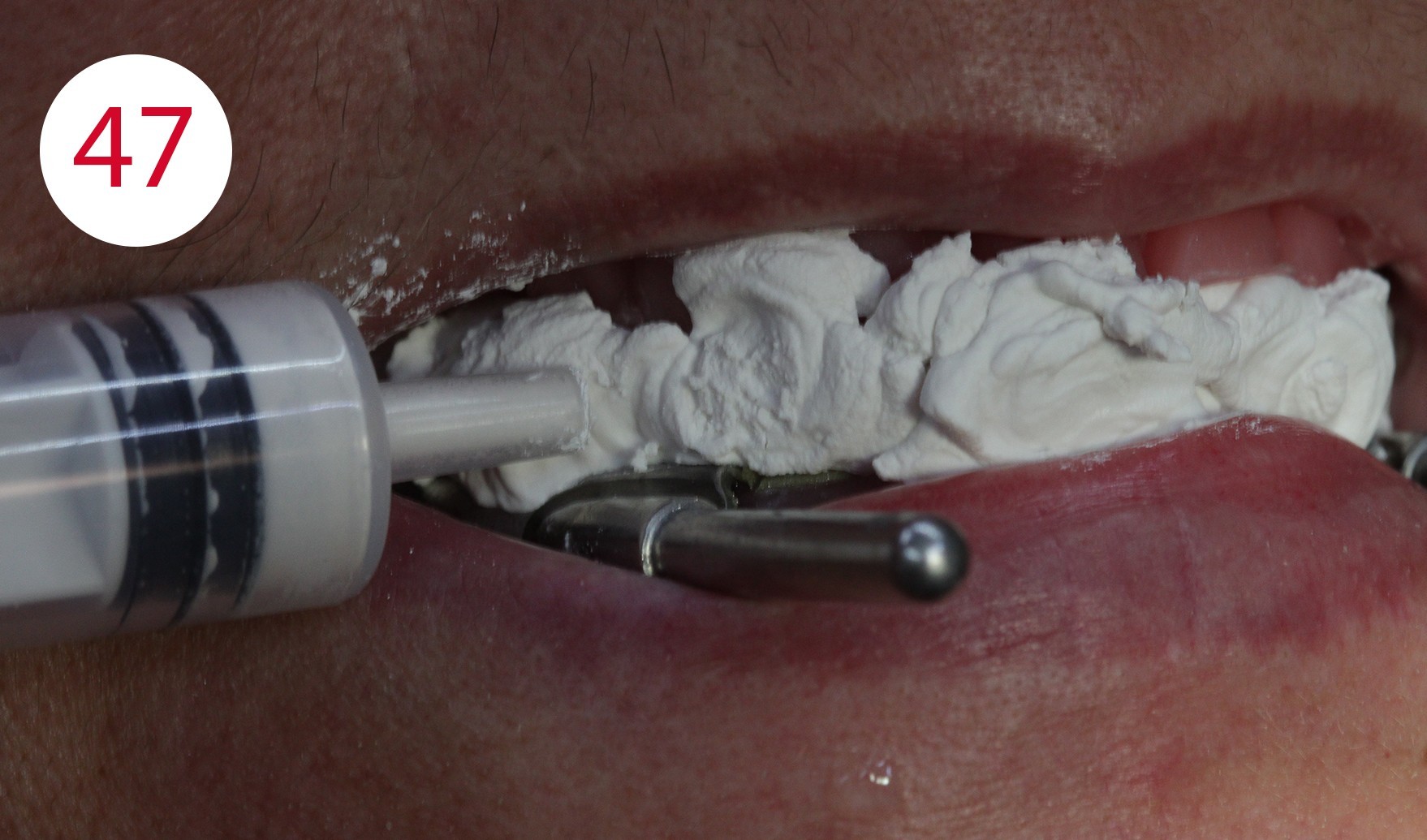
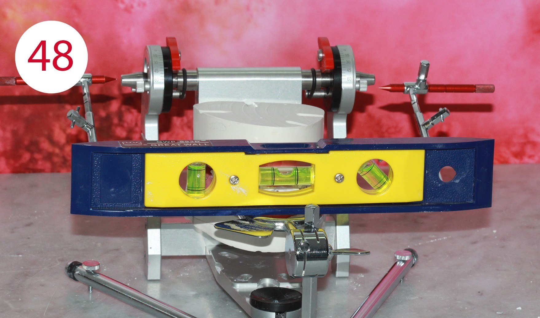
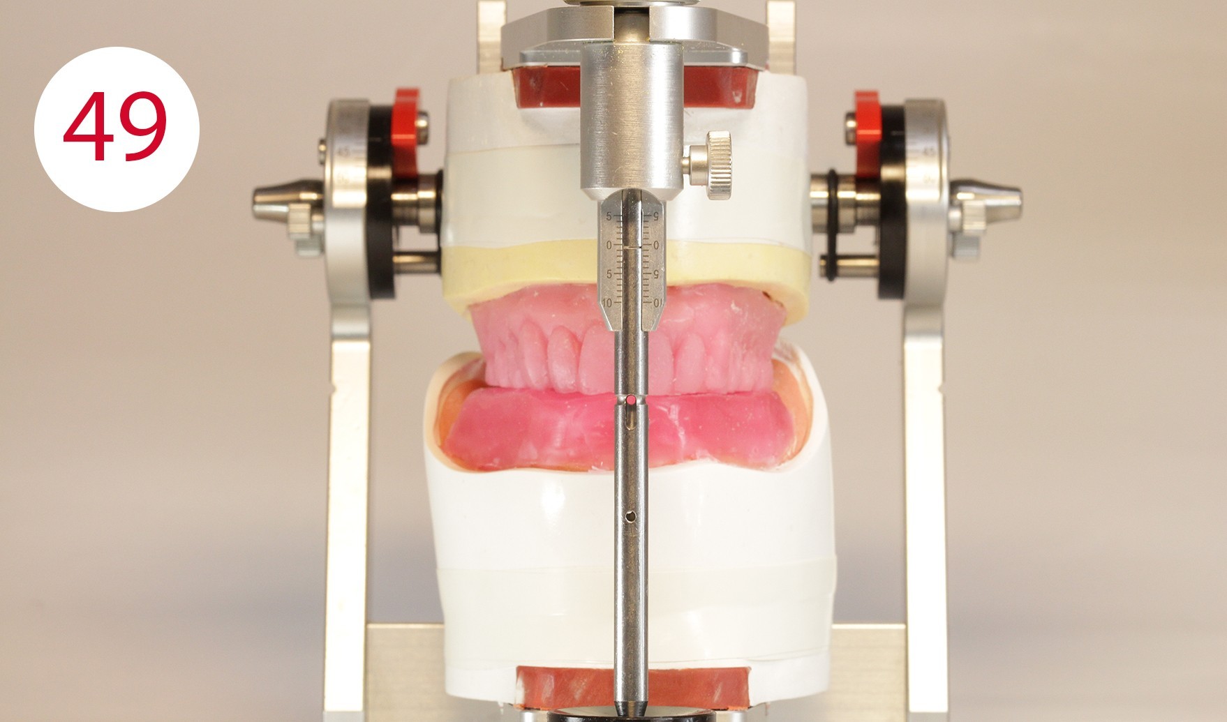
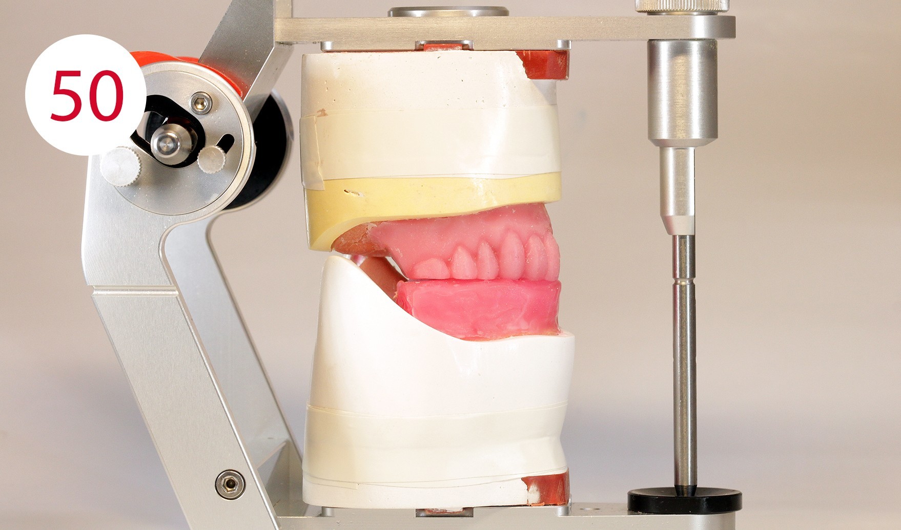
Finally, this position is keyed, in this case with fast setting articulator plaster, which was filled into a syringe for application beforehand (Fig. 47). Once the registration templates are keyed, they are transferred to the articulator (Fig. 48). To transfer the models into the articulator, the writing leads are replaced by metallic reference rods on the GERBER facebow. When positioning their tips in the hinge axis of the articulator, it should be ensured that the metallic reference rods are always parallel to the working plane. During the curing of a low as possible expanding plaster and after removing the wax from the two metal plates (supporting pin and writing plate), the existing silicone keys were used in the upper jaw to restore the part removed for the supporting pin registration and to bring it into contact with the lower wax wall (Figs. 49, 50).

Model analysis
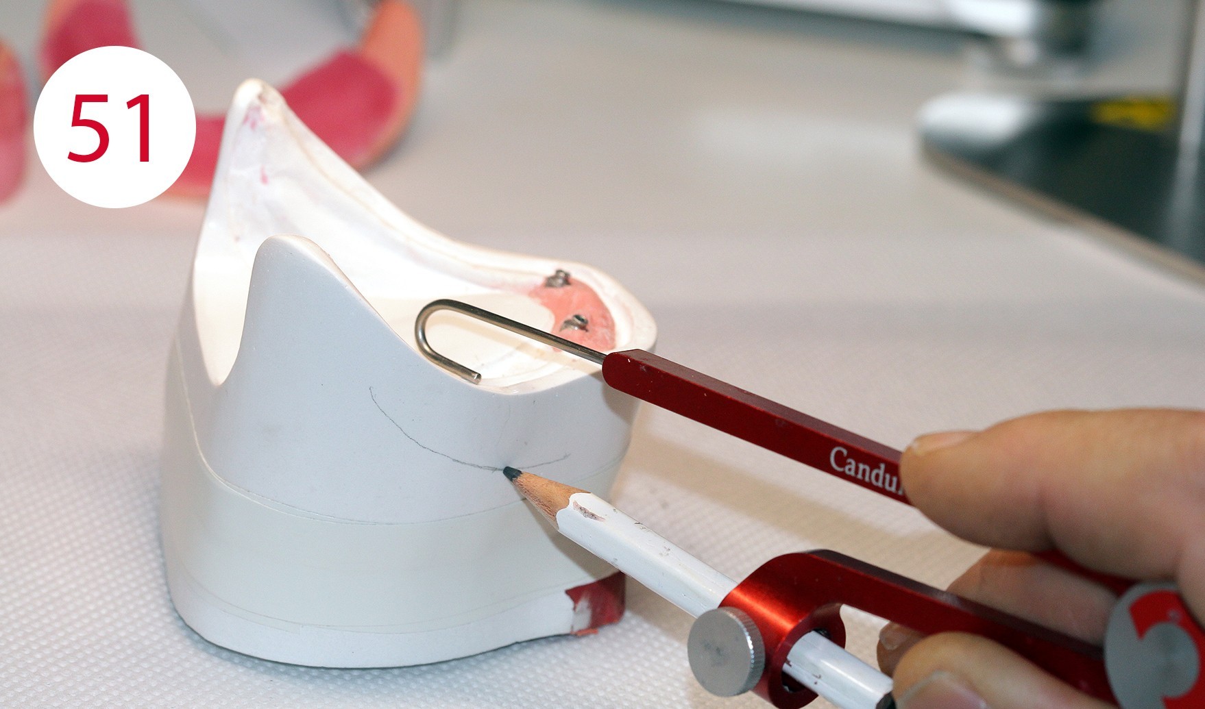
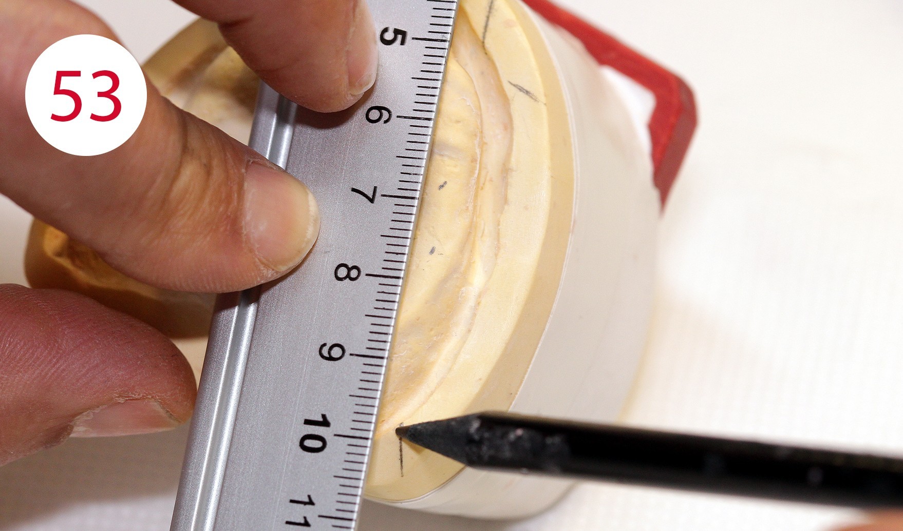
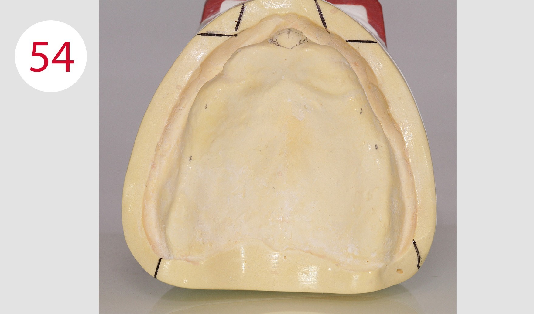
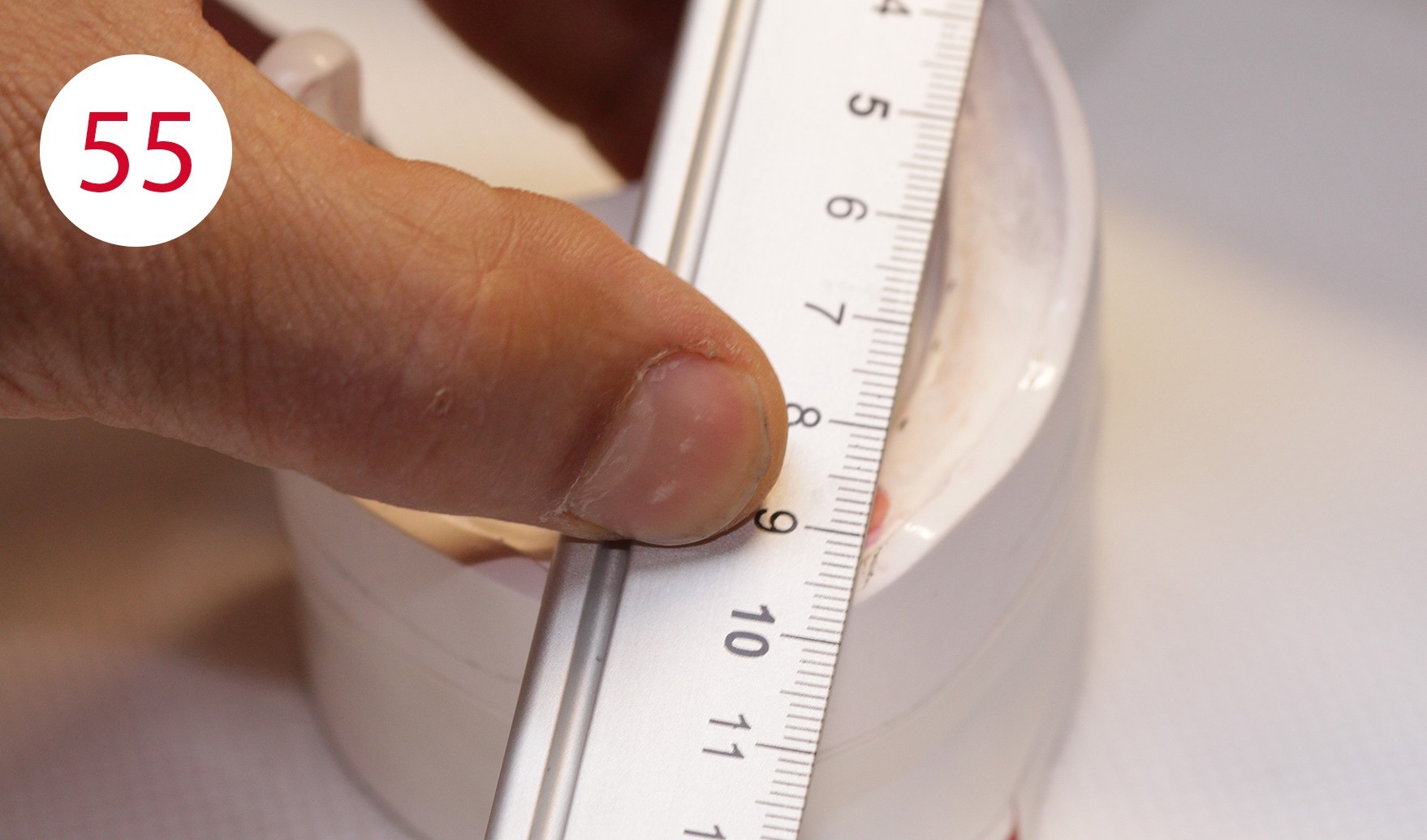
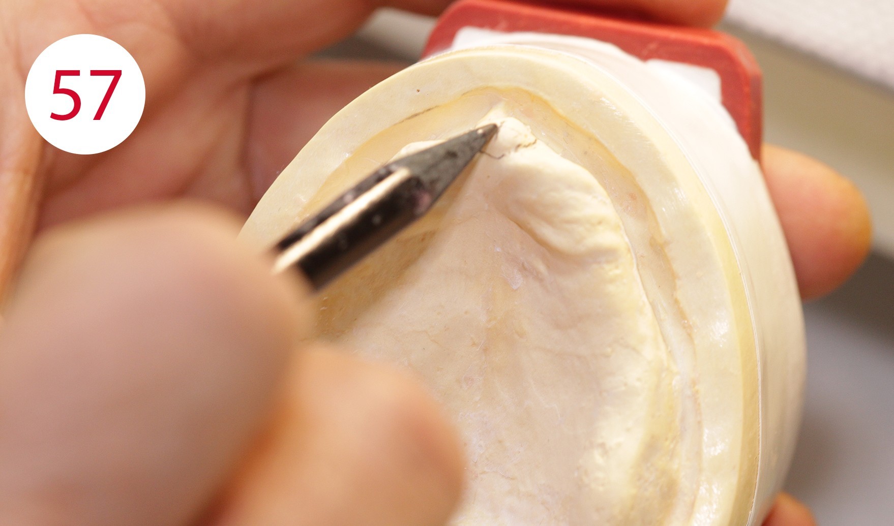
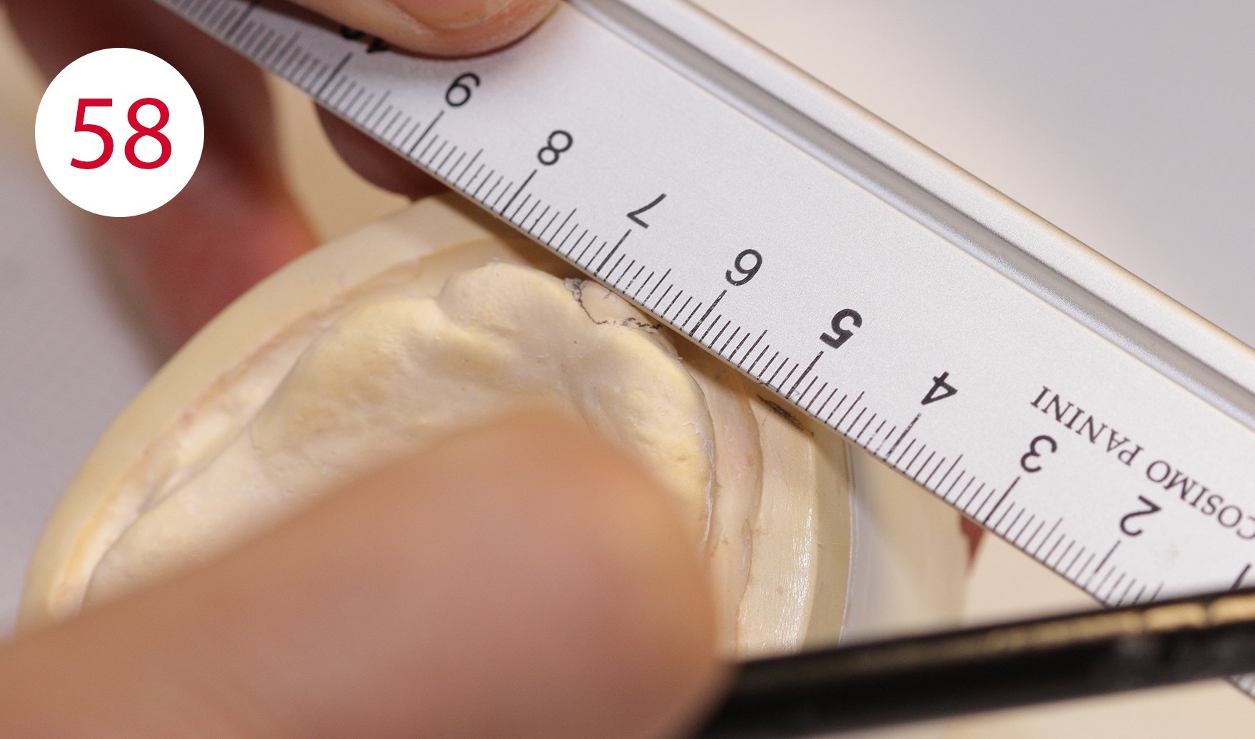
The "blueprint" in the form of the model analysis for the wax-up was then prepared in the laboratory. For this purpose, the contour of the alveolar ridge on both sides is transferred to the outer surface of the mandibular model using the profile compass (Figs. 51, 52). The 4 and 6 positions are marked and also transferred to the model outer surface or model margin (Figs. 53, 54, 55). The center of the incisive papilla is determined for the CPC line, the line is extended to the model margin (Figs. 57, 58). This is followed by checking the bilateral ridge profile to determine parallelism or divergence. The stop line is also determined. According to GERBER, in order to avoid forward movement during sagittal frontal and caudal gliding behind this, it is necessary not to set up a masticatory unit in occlusion any more, which would also lead to premature wear of the retention part in our case due to the implants.
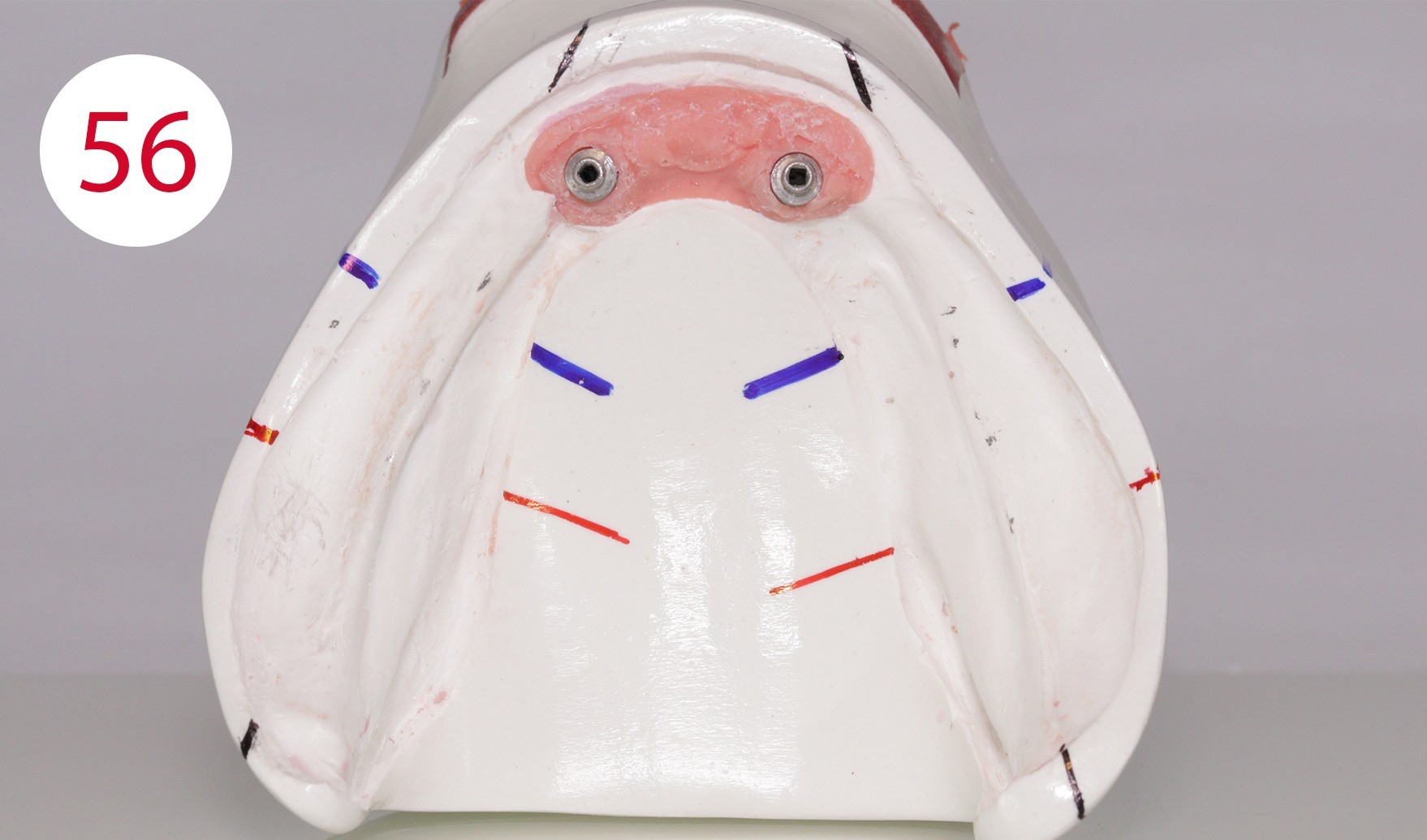
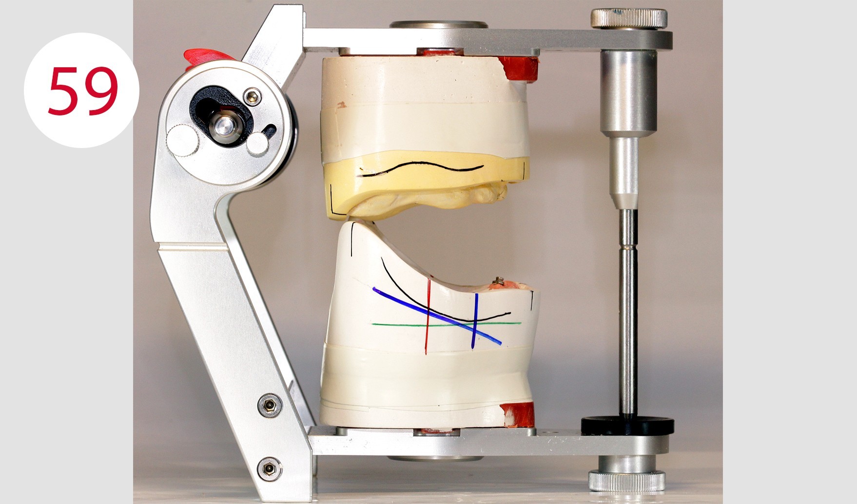
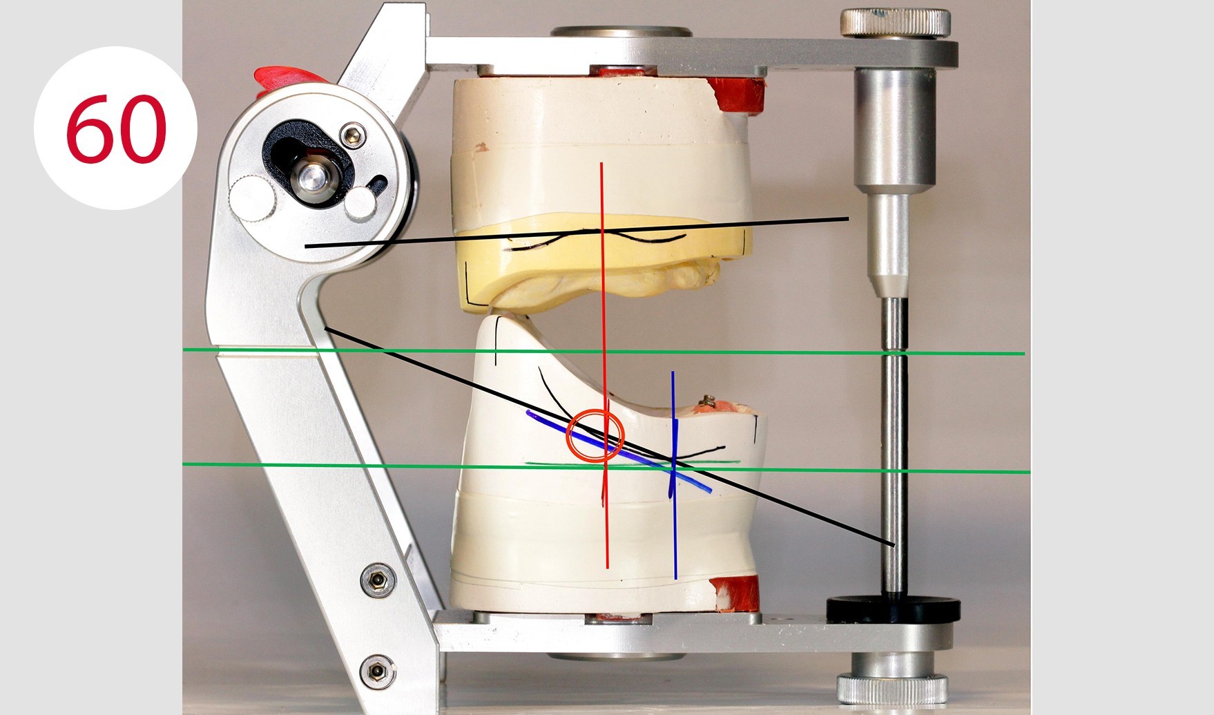
In the next step of the model analysis, it is assessed whether a normal or a cross bite is present and it is checked whether the alveolar ridge has a distal or a lingual position (Fig. 56). Of course, an experienced eye can detect the situation to be solved in a few minutes and a few work steps in order to recognize how and where anterior and posterior teeth are to be set up. However, it makes sense to record and document as much information as possible. This way, it is possible to make the design of the dental prosthesis more predictable during the set-up phase (Figs. 59, 60) despite the somewhat higher expenditure of time and also to avoid errors.
Fig. 60: Black lines = sagittal corridor of the alveolar ridge / Green lines = references for the Camper's plane / Vertical blue line = lowest point of the residual alveolar ridge / Angled blue line = reference line at 25° / Red line = stop line / Red circle = stop line exceeded because the red line exceeds the 25° given by the angled blue line
Wax setup
Following model analysis, the teeth were set up according to the "condyle theory" formulated by GERBER. Also and in particular for the patient to be treated here, the posterior teeth in tooth-to-tooth occlusion were chosen consistently following the GERBER concept.
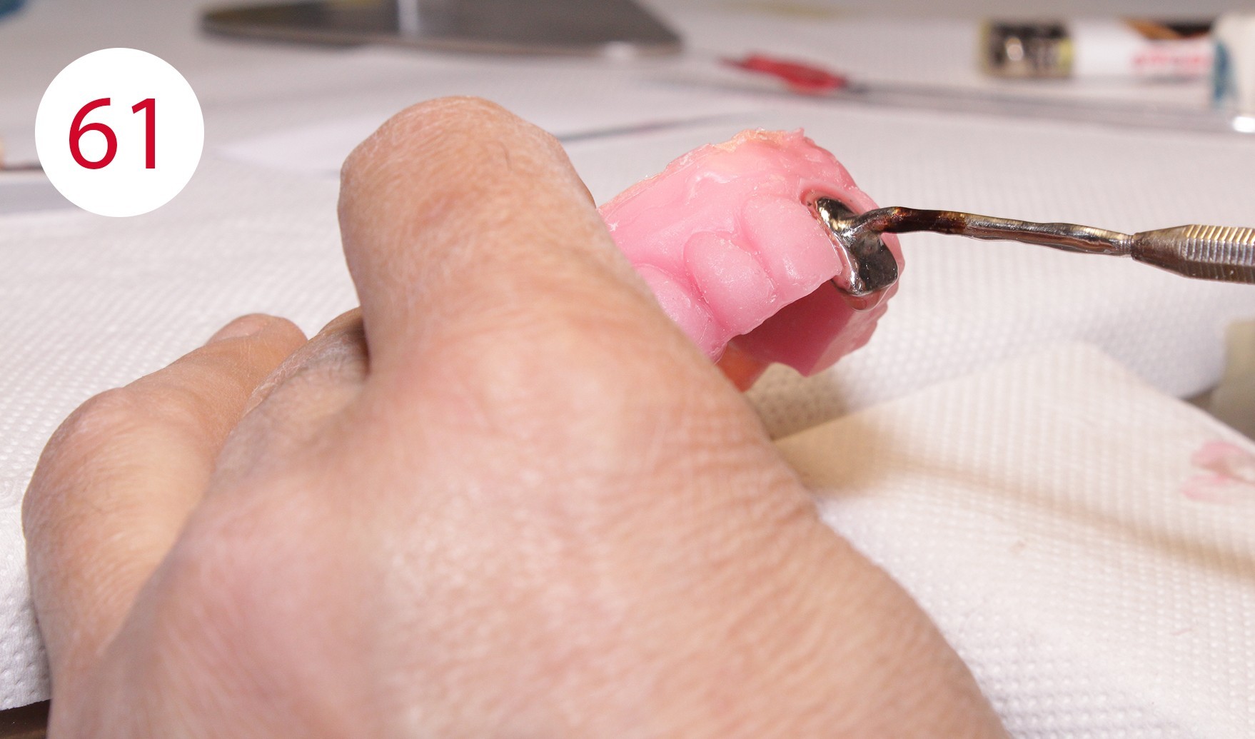
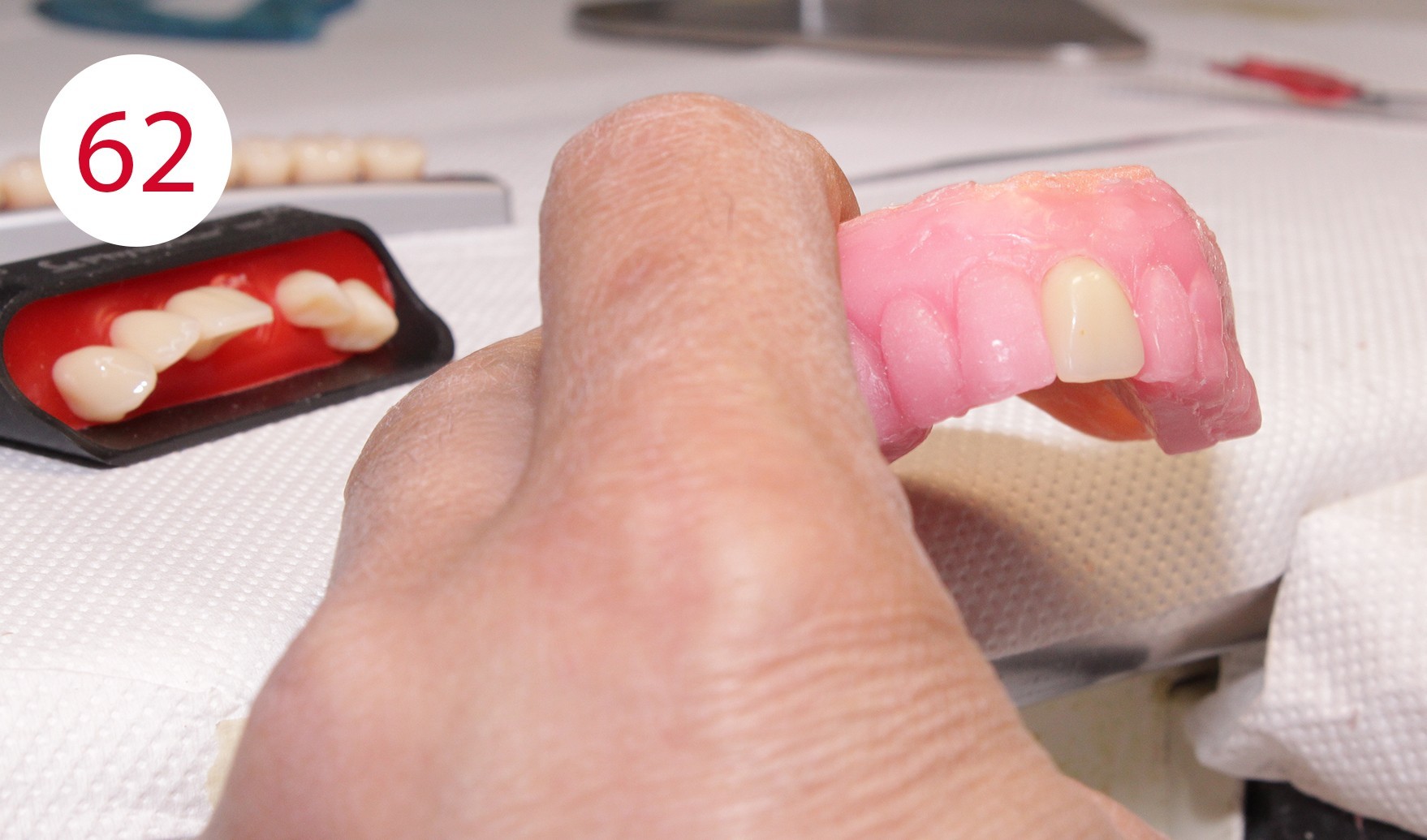
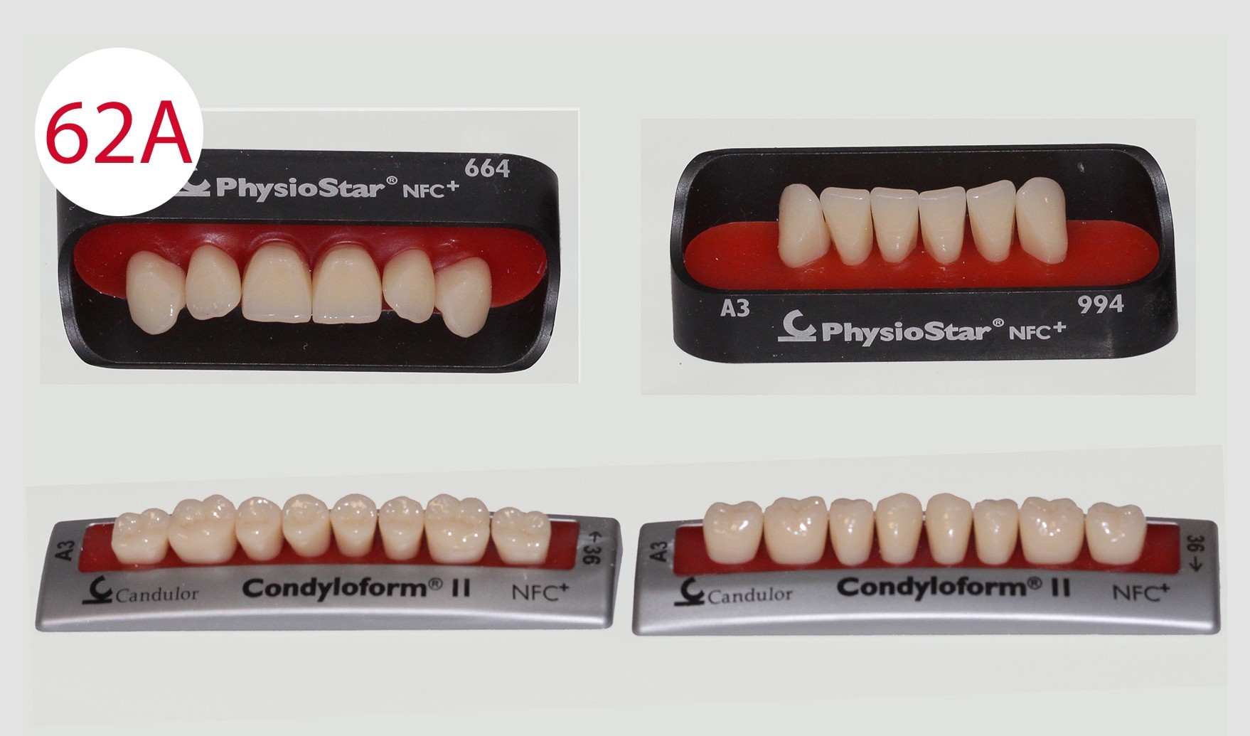
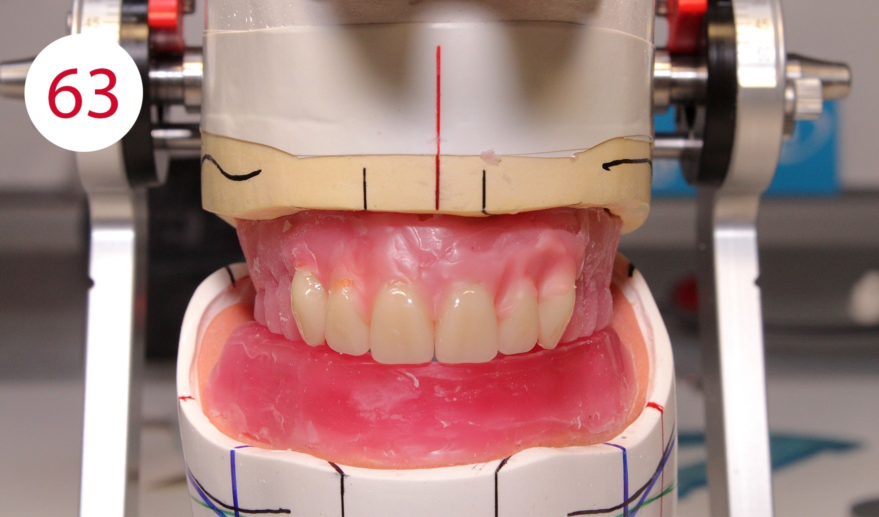
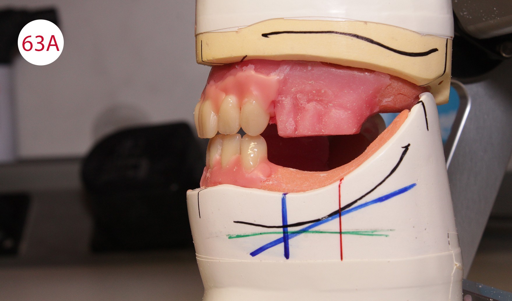
During the preceding functionalization of the previous prosthesis, an identical wall was constructed on the temporary prosthesis. Therefore, the lines of the wax wall could be followed when setting up the teeth. To this purpose, a practical aid was developed in the laboratory for setting up upper incisors for "wax wall set-up", where the wax is heated specifically locally and the artificial incisor is set up quickly (Figs. 61, 62, 62A). This procedure was repeated up to the canines (Fig. 63). Subsequently, the lower anterior teeth and then the canines were placed in superimposed alignment (Fig. 63A).
Posterior tooth placement was performed as noted with posterior teeth according to the GERBER concept in a tooth-to-tooth relationship, which occluded lingually according to the mortar-pestle principle in the BC contact scheme. This approach is based on the condyle theory that the occlusal surfaces reflect the inverse mirror image of the condyle-fossa relationship. Exceptions are the first premolars whose lower buccal cusps occlude in the upper fossae as is the case with the CONDYLOFORM posterior teeth (CANDULOR) used. The posterior teeth were placed following the upper wax wall, starting with the first lower premolar with reversed mortar-pestle principle, which were placed slightly above the occlusal plane. The GERBER method attaches particular importance to the set-up of these two dental units. As the premolars are closest to the canines, the lower supporting buccal cusps (reverse mortar-pestle principle) only have a punctiform contact in the upper fossa. This promotes a stronger cutting effect of the canines. As the first premolars are set up such that the forces are shifted to a central area of the alveolar ridge located further back which is more suitable for masticatory loading, prosthesis stability is increased. This would not be possible if the canines were to achieve a tearing effect and not a cutting effect as with the PHYSIOSTAR anterior teeth (CANDULOR).
Left row of posterior teeth
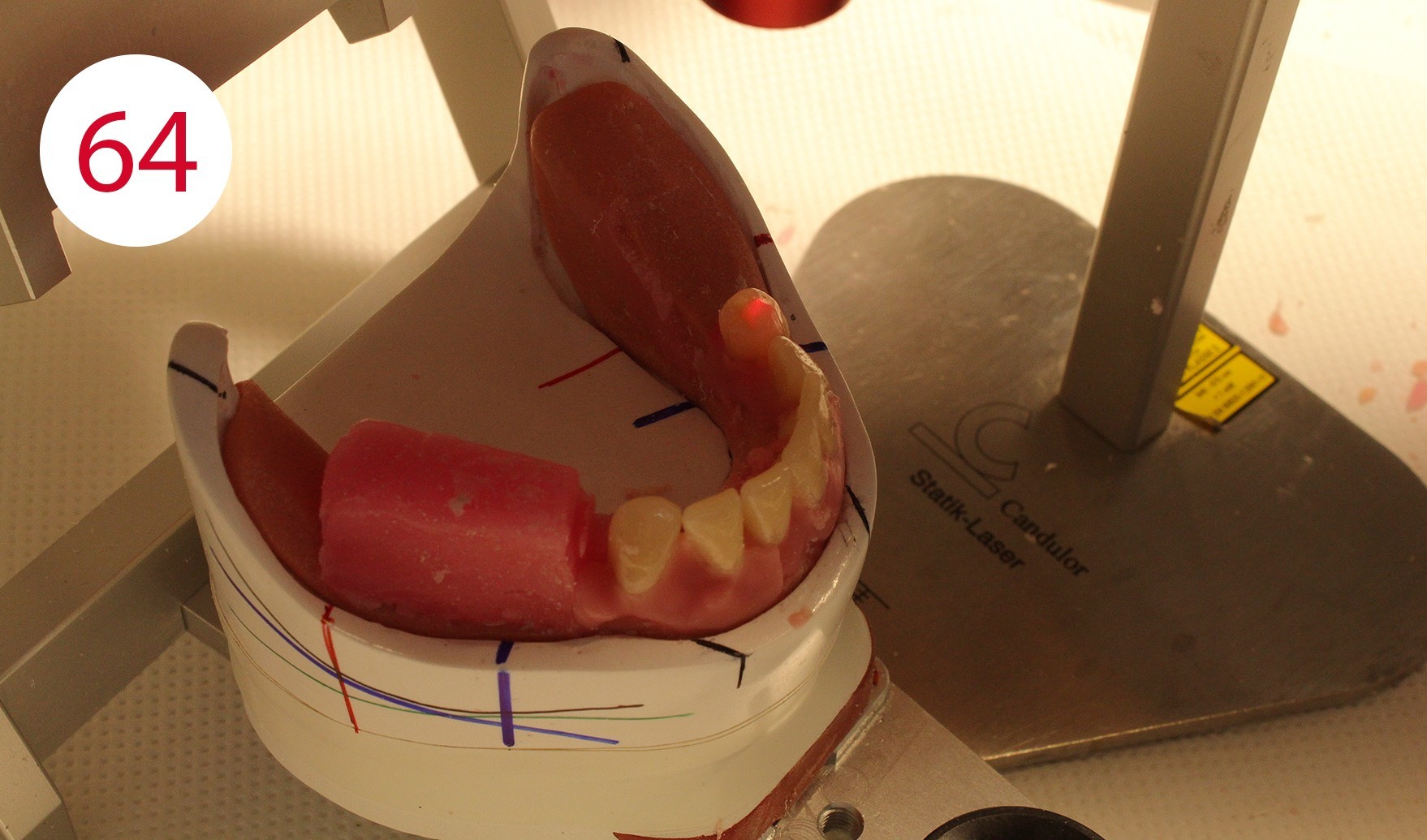
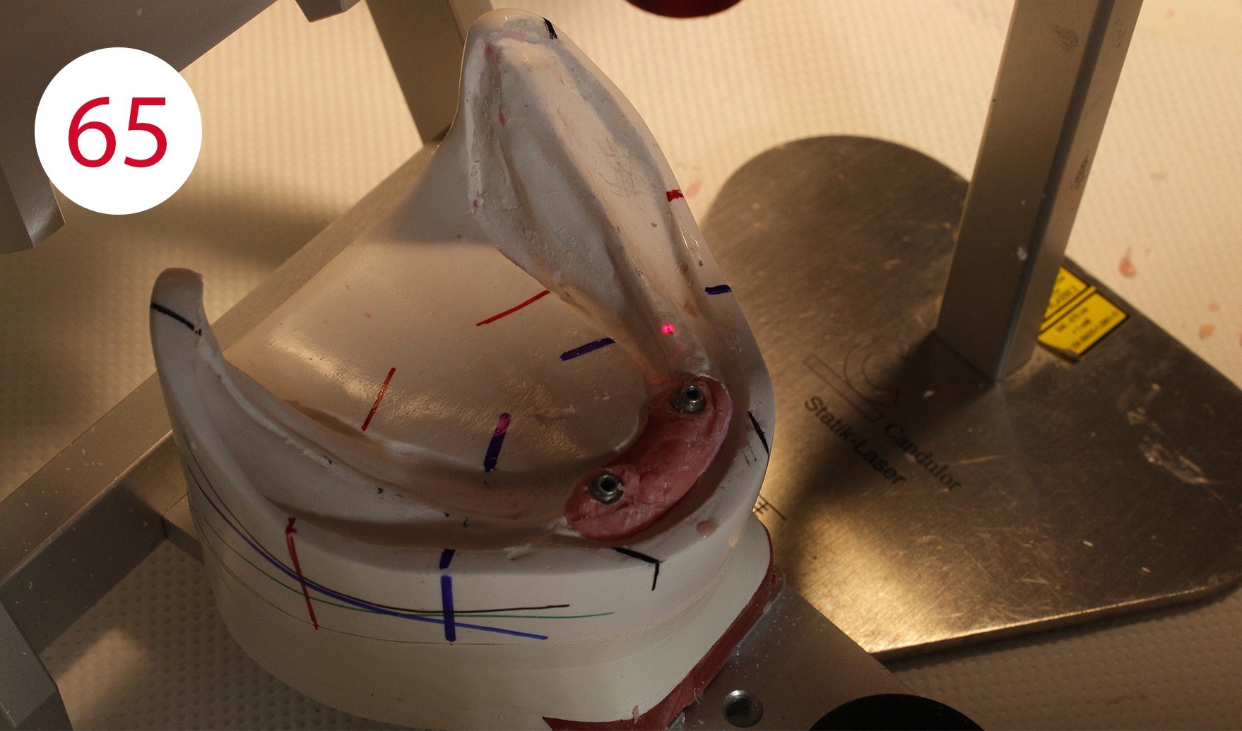
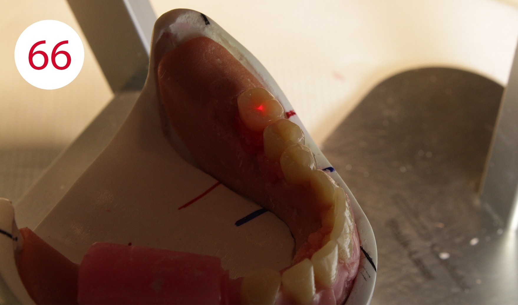
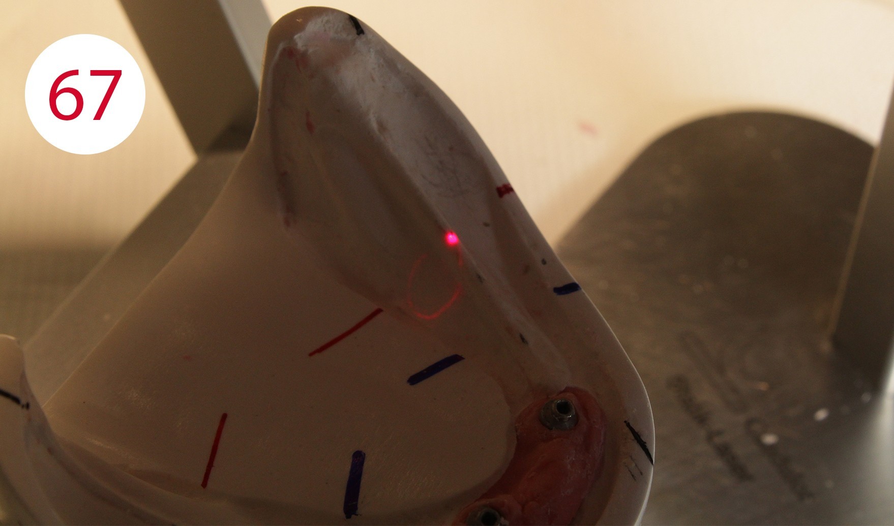
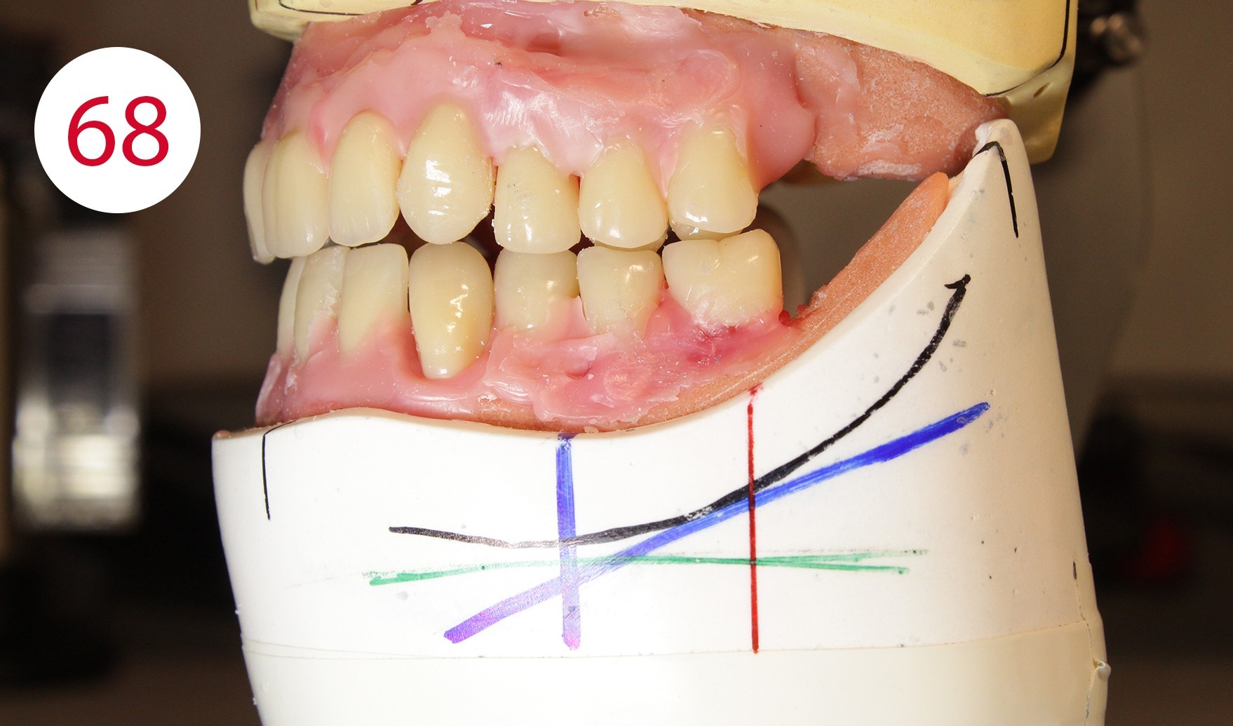
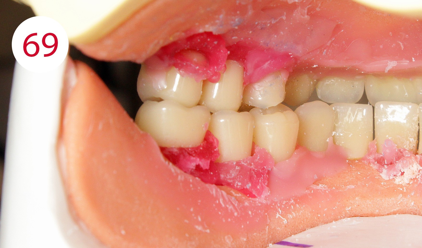
Following the upper wall further and with a view to making only the palatal cusps effective as support cusps, the second premolars and the lower molars were set up. According to the GERBER concept, the force should always be directed perpendicular to the residual alveolar ridge. In practice, the set-up follows the alveolar ridge corridor or static line, which is marked as a black line on the margin of the model. The STATIK POINTER (CANDULOR) (Figs. 64, 65, 66, 67) is suitable for precise and reliable control as its light point directs the occlusal force direction of the tooth onto the static line and thus onto the alveolar ridge, and can therefore be used quickly and unambiguously to achieve autonomous chewing stability. This is followed by setting up the upper molars. According to the position of the stop line and taking into consideration the implant support of the lower overdenture, it seemed reasonable and functionally appropriate in this case to dispense with an upper first molar on the left side and to set up another second upper premolar (Figs. 68, 69). The reason being to direct the chewing force in parallel to the red stop line as a boundary line for the beginning rising lower jaw branch and thus to steer it statically stable to the lower jaw ridge in order to avoid forward movement. This generally applies to the lower jaw, but it cannot be ruled out - especially in the case of a KELLY syndrome - that it may also be appropriate in the upper jaw.
As shown in the case described, it may be necessary to place the set-up differently on one side from the other, following the same basic rule - autonomous chewing stability - in variants.
Fig. 69: Lingual occlusion view
Right row of posterior teeth
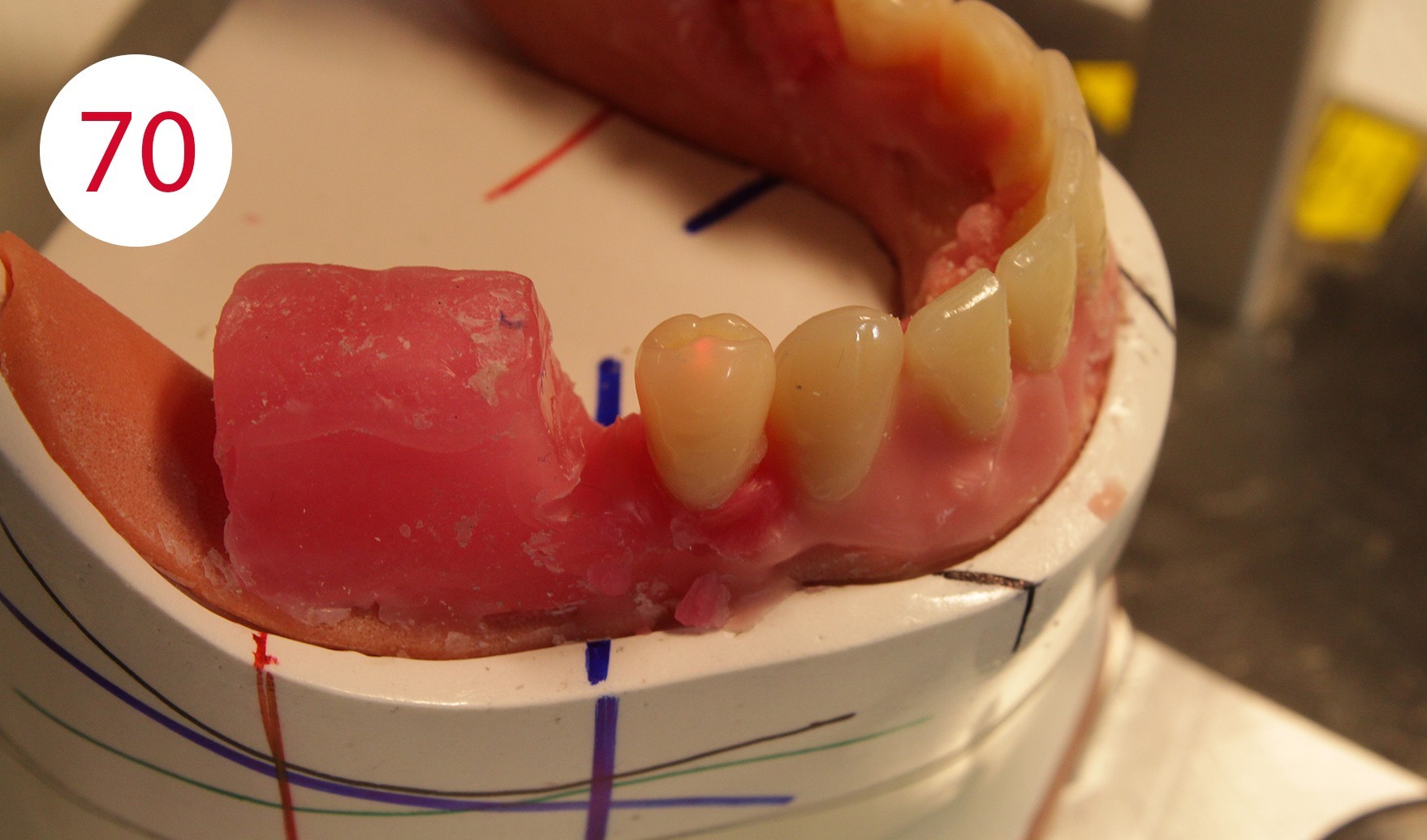
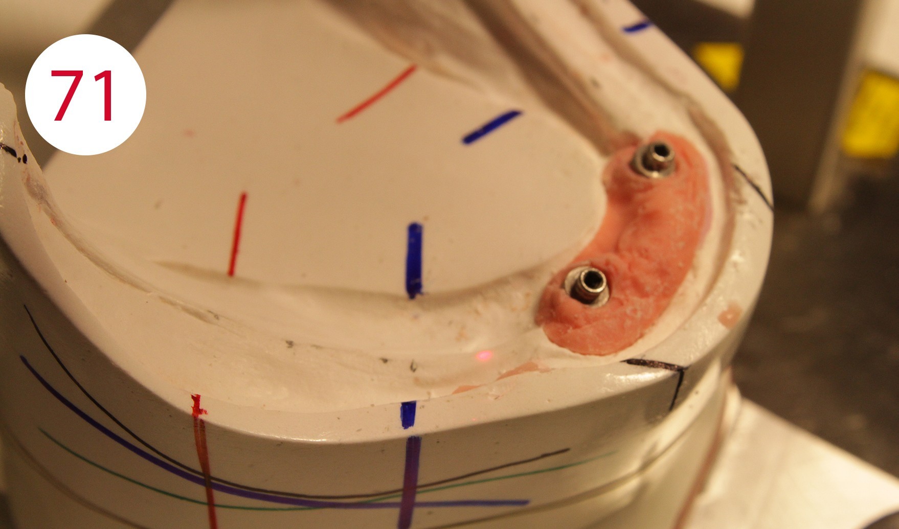
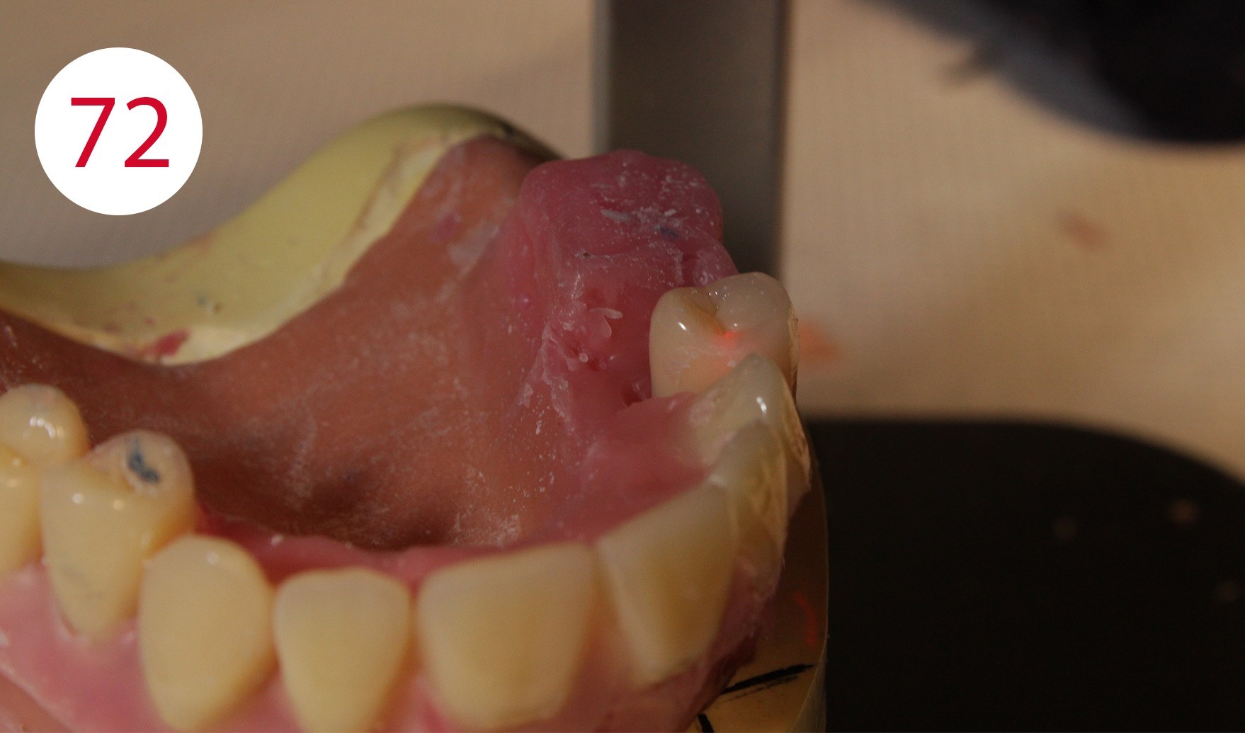
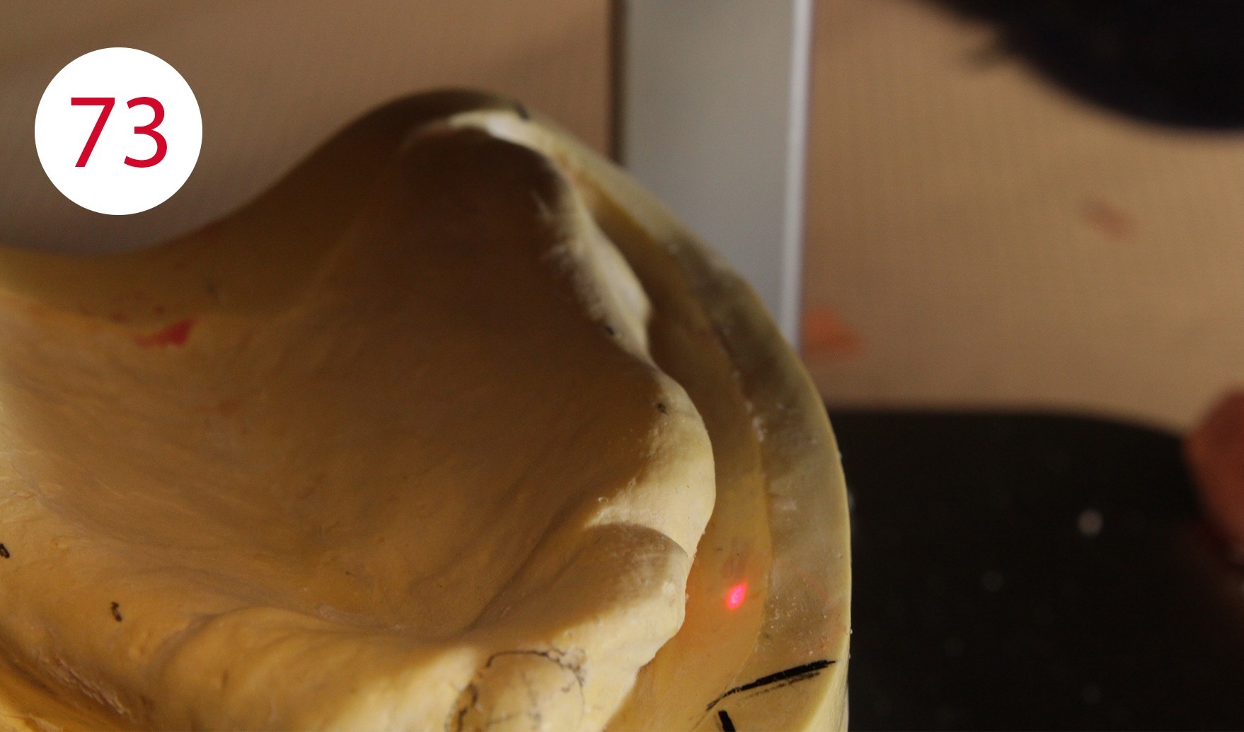
For example, when setting up the lower right first premolar in the centric, it would have been necessary to place it significantly further in lingual position to direct the force on the antagonist (tooth 14) to the middle of the ridge (Figs. 70, 71, 72, 73). However, this would have questioned its cheek contact and prevented reaching the neutral, chew-stable zone. Setting up teeth on atrophied and incongruous alveolar ridges often means not having sufficient contact with the cheek and narrowing down the active range of the tongue.
Under these conditions, a free space is created between the cheek on one side and the artificial teeth as well as with the outer surface of the prosthesis body. On the one hand, food particles accumulate in this region and it becomes difficult for the cheek to return or transport these to the chewing area or chewing tube. The free space between the cheek and teeth also prevents the cheek muscle (M. buccinator) from neutralizing the outward force exerted by the tongue. The neutral zone of natural dental arches is formed under the influence of genetic factors and forces exerted by the muscles of the tongue, lips and cheeks during tooth penetration. The work of muscles lasts a lifetime and continues even after the loss of teeth or chewing units. If the latter are lost, a free space is created in the oral cavity, the so-called "intermaxillary space", an area in which the "neutral zone" is located. This area can be defined as the area in which the outward directed forces of the tongue are neutralized by the inwards directed forces of the cheeks and lips during chewing. These forces exert their effect not only when chewing, but also when speaking and swallowing.
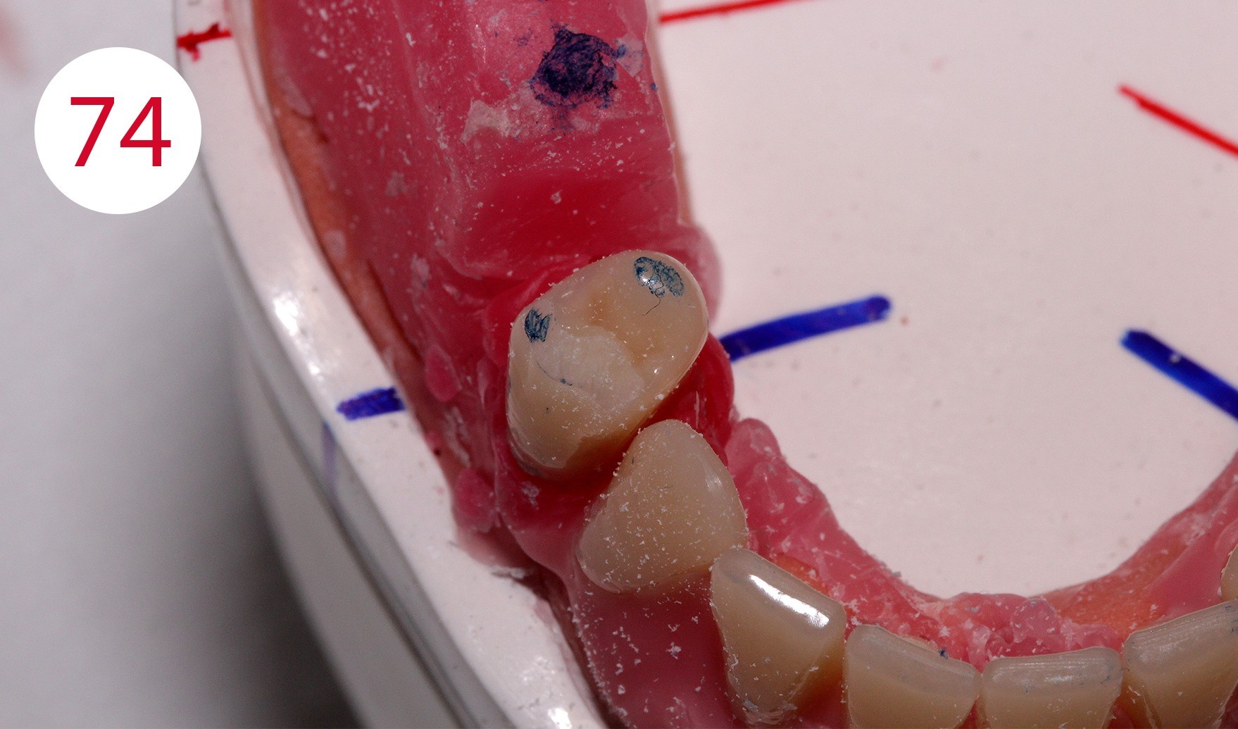

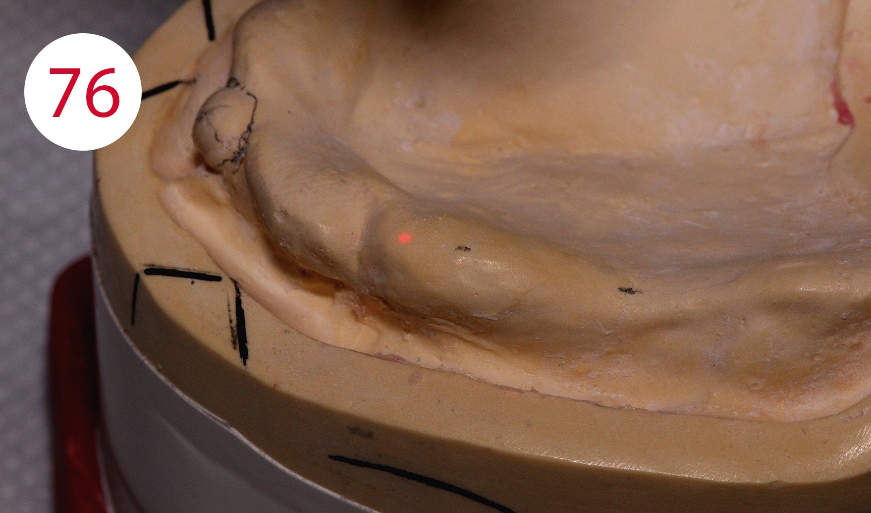
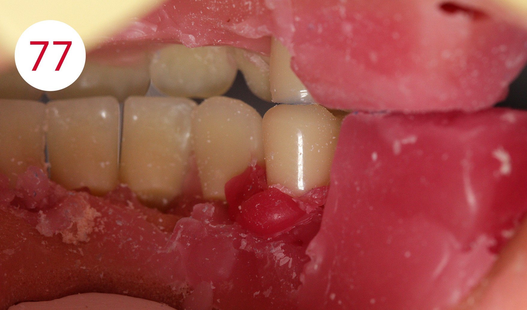
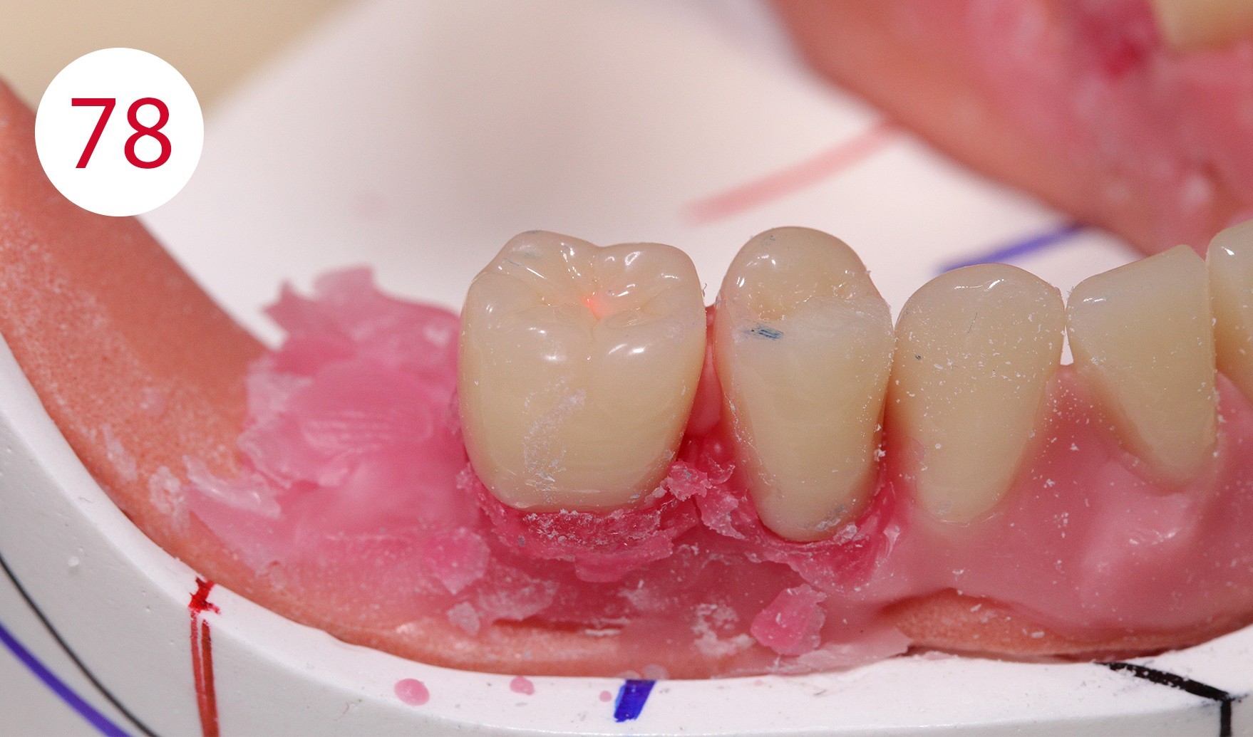
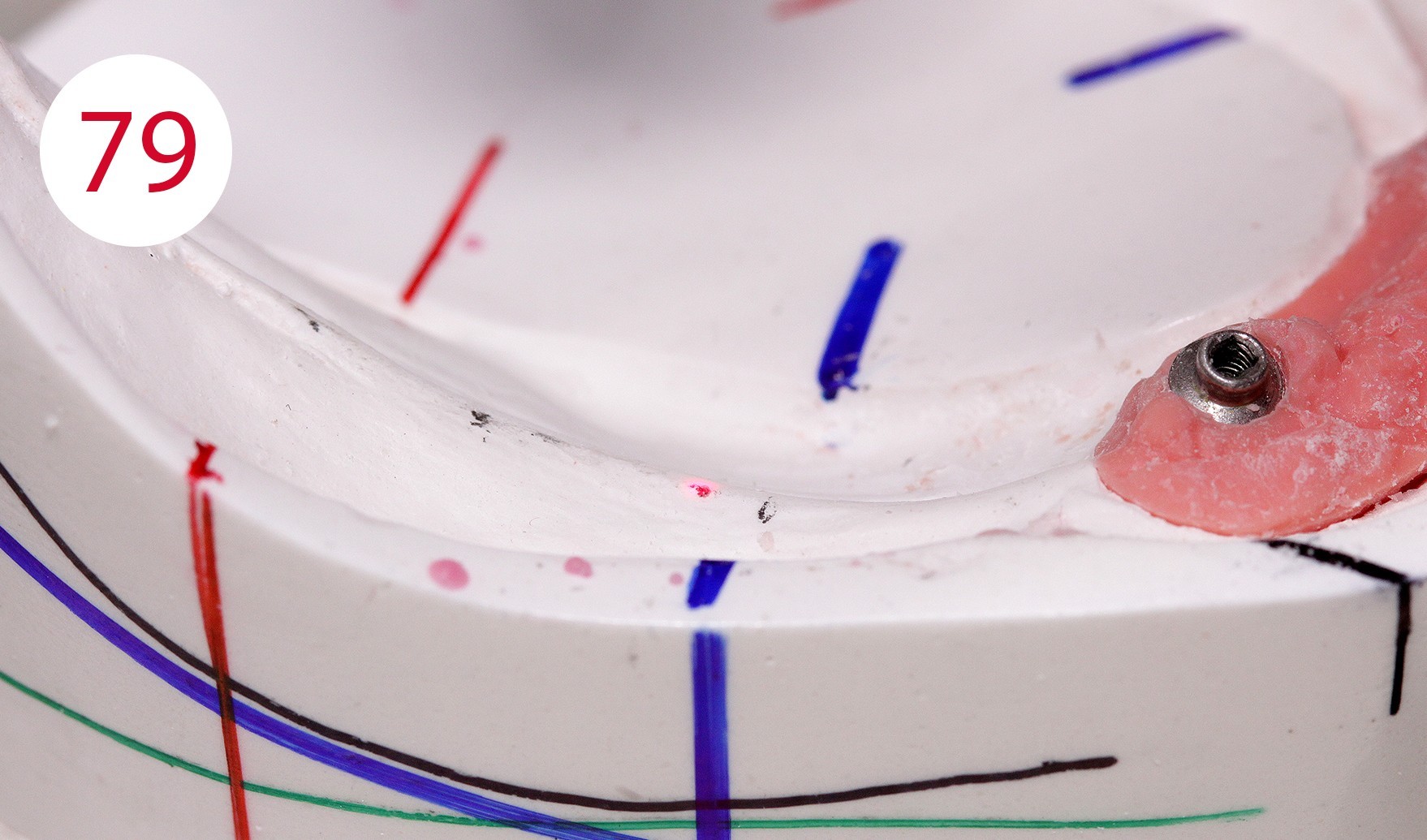
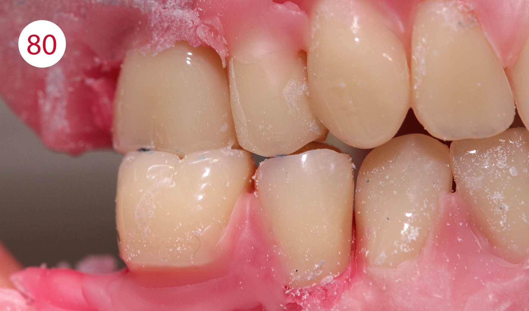
It is therefore very important to set up or dimension the artificial teeth and the outer surfaces of the prosthesis within the neutral zone, as ignoring this would expose the prosthesis to continuous horizontal thrust, which could have caused further damage to alveolar ridges, as given in this patient due to the previous insufficient restoration. To achieve a statically correct occlusal contact as well as a myodynamically sufficient cheek contact, we decided to depart from the usual set-up schemes and set up an upper right 5er instead of the lower right 4er (Figs. 74, 75, 76, 77). The objective being to maintain statically stable conditions for both sides. In addition, the increase of the lower jaw branch on this side of the jaw required sacrificing the first premolars (Figs. 78, 79, 80). The set-up on this side of the jaw was performed statically consistent in the cross bite, i.e. the lower buccal cusps were ground recessed for the upper buccal cusps as support cusps.
Fig. 77: Lingual occlusion view
Construction of the anchorage for the lower overdenture (MDT Salvatore Chimenz)
Following the esthetic try-in, one proceeds to the retention phase, the adaptation of the spaces for the lower part of the dentures. The choice of the occlusal plane for autonomous chewing stability has been explained and therefore we have chosen an implant-supported, mucosa-based retention system. The implemented solution is the simplest in terms of safe retention, advantageous in terms of stability and acceptable to the patient from a psycho-physical point of view.
Based on this principle and the clinical situation, the attachments must not compensate for sagittal sliding movements, the so-called "forward movement" of the prosthesis body, as would have happened with loading on an inclined plane due to premature wear of the retention part, the caps and with the risk of the denture failing (Fig. 80A). Two titanium posts with patient-adapted transmucosal profile (Fig. 81) in the form of the RHEIN 83 with Ot equator abutment were prepared, on which a passive bar with SEEGER system was fabricated.


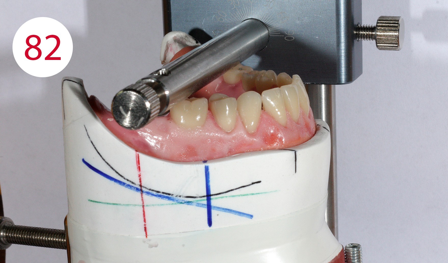
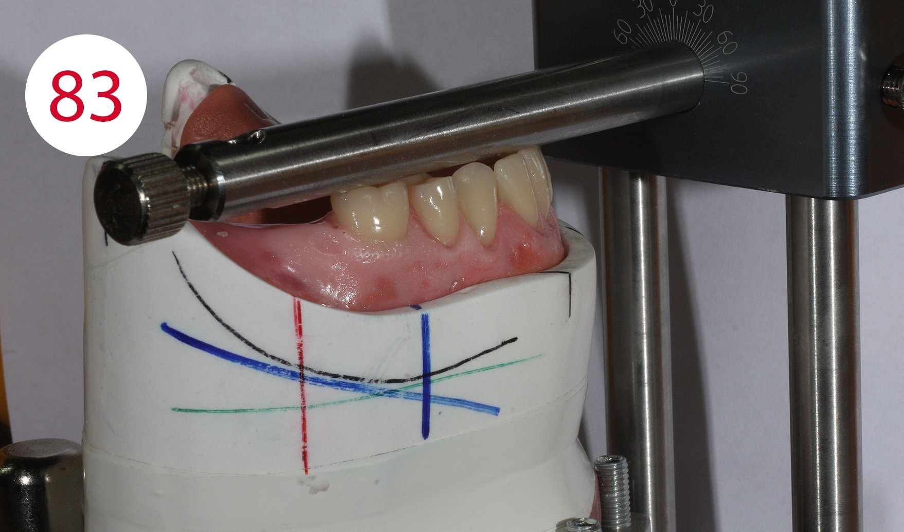
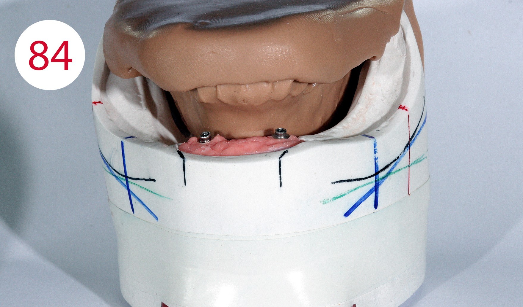
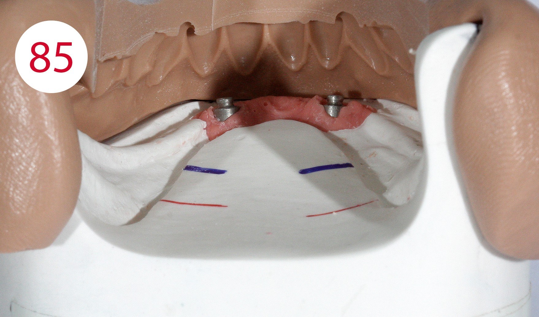

The insertion direction was determined for the bar construction (Figs. 82, 83), which in our case coincided with the occlusal plane. This condition is necessary to allow the abutments to work horizontally and to prevent premature wear of the retention part. After fabricating two silicone masks for the lingual and vestibular sides to determine the remaining free spaces (Figs. 84, 85) into which the bar and the reinforcing counterpart were to be inserted, the polymerizable SEEGER containers (Fig. 86) were positioned and connected to autopolymerizing modelling resin so that the bar could be shaped. After curing, the bar was separated and the resulting segments connected with a small amount of acrylate to achieve maximum retraction control.
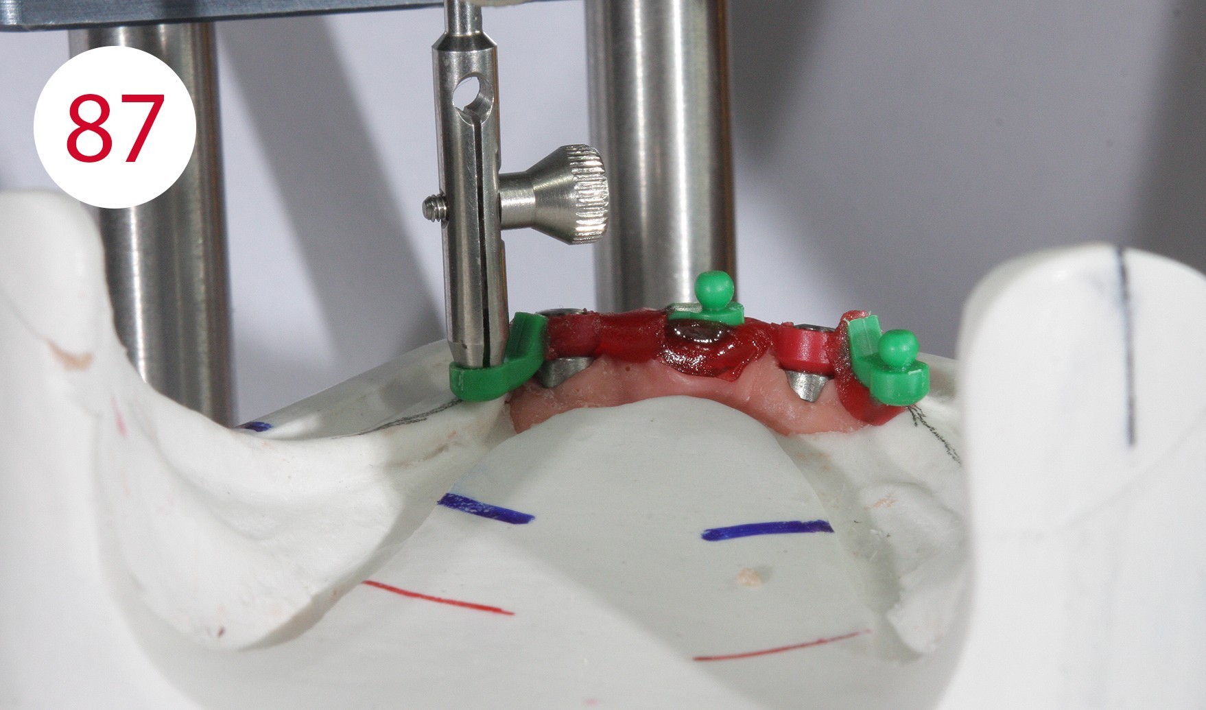
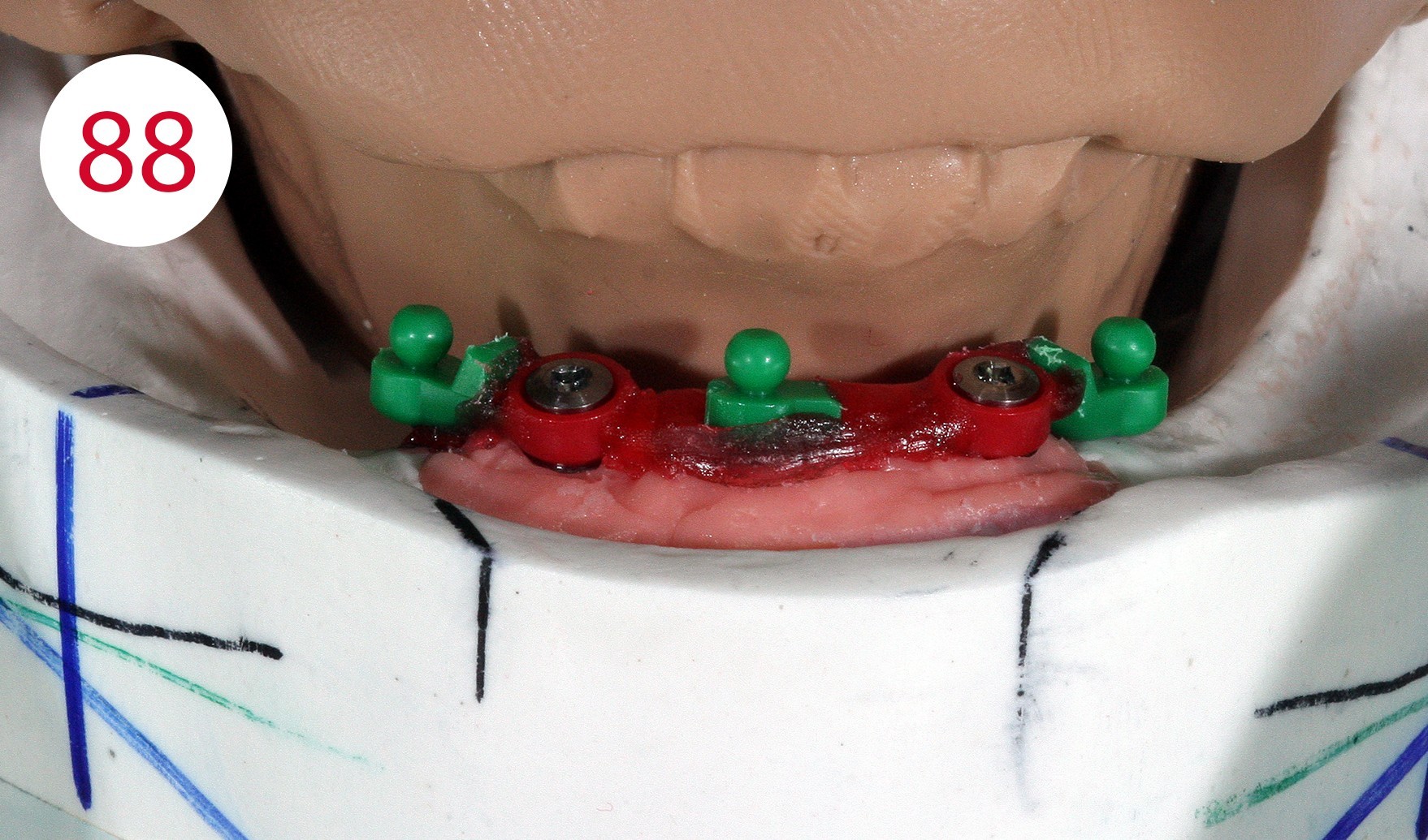
With the aid of a parallelometer the polymerizable Ot Cap Normo attachments with external threads were mounted (Figs. 87, 88), which compared to other systems have a flat head ball and an elastic cap with a spherical interior. This allows for vertical yielding when chewing, which in some cases harmonizes with the yielding of soft tissues, also due to the sensitivity of the nylon caps, which behave adequately in moist environments.
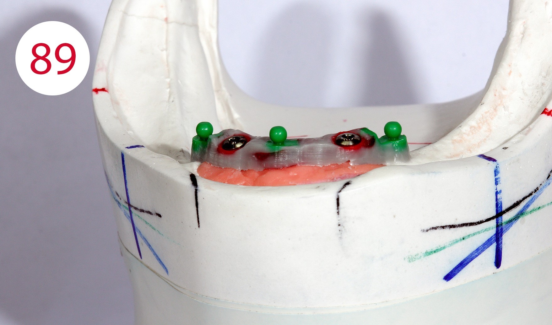
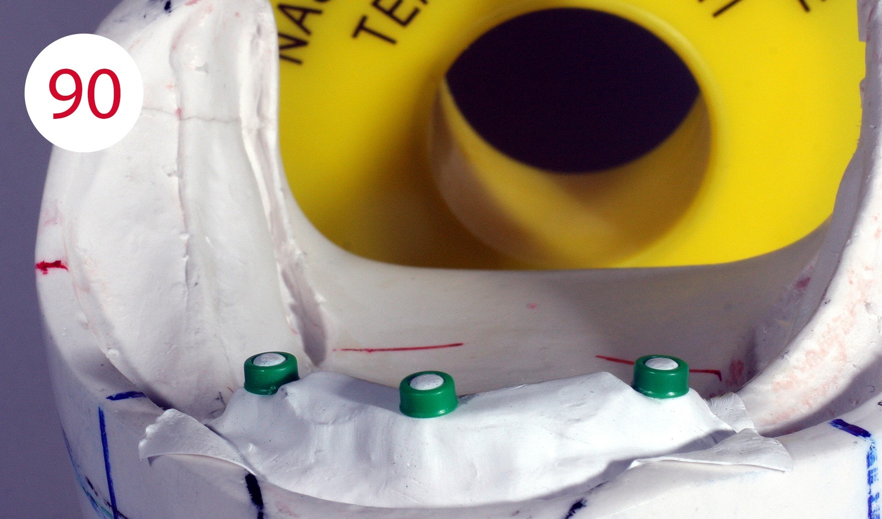
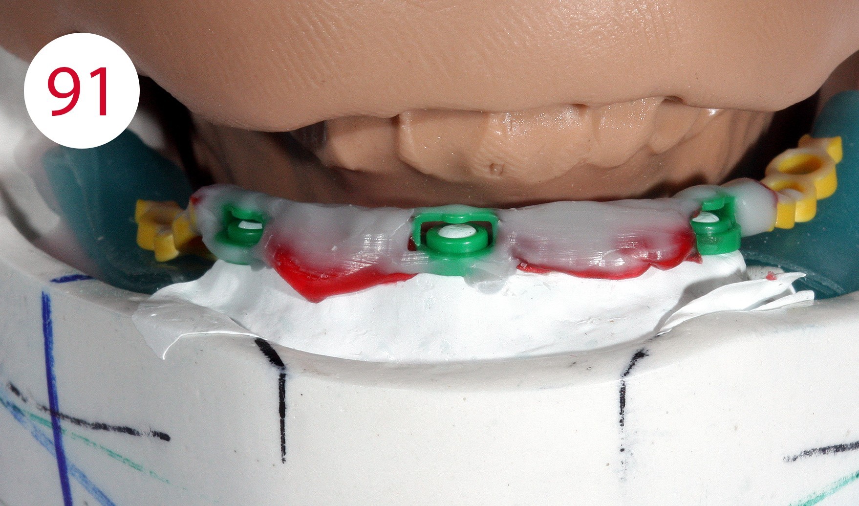
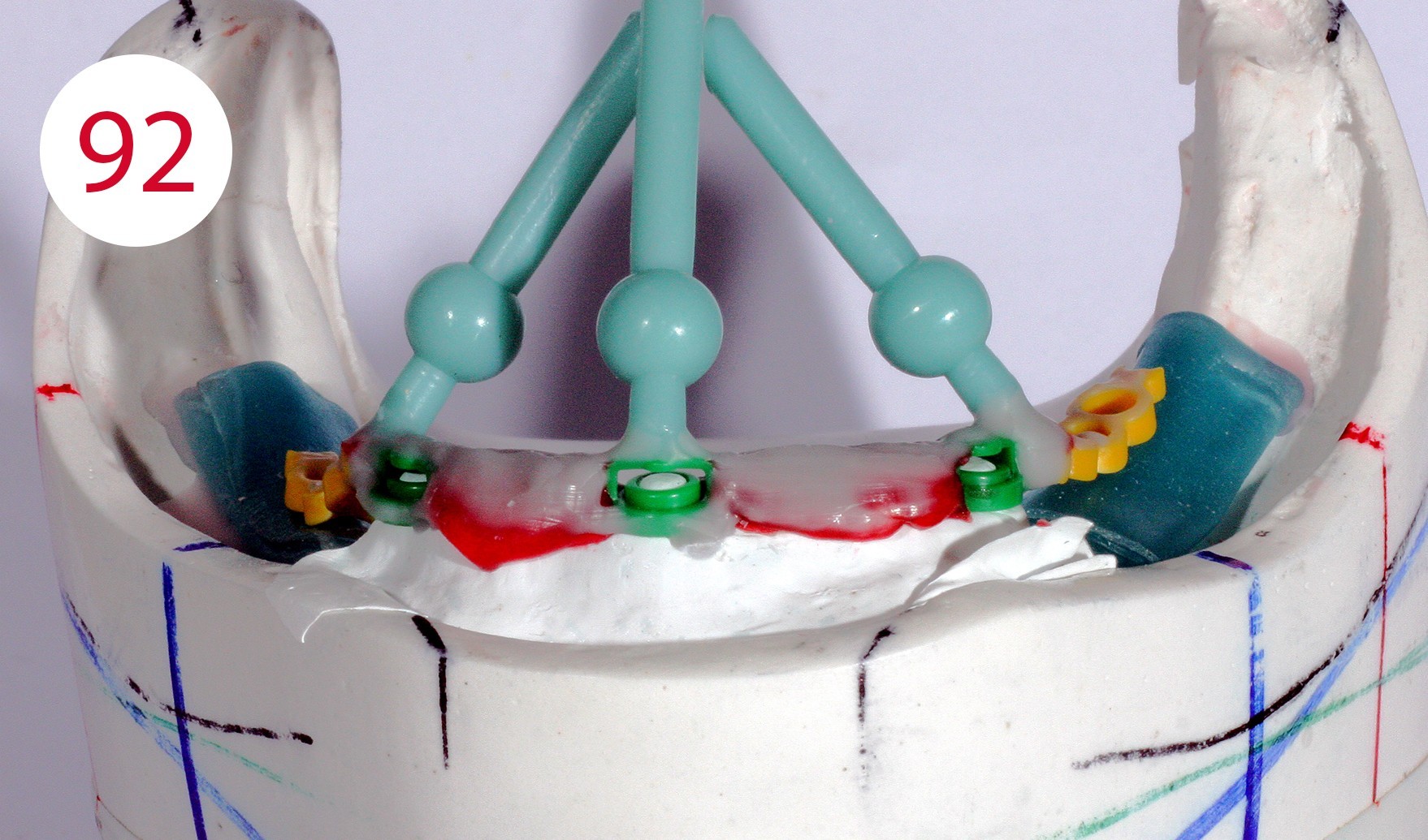
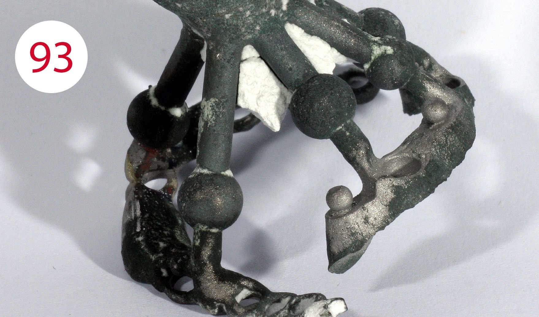
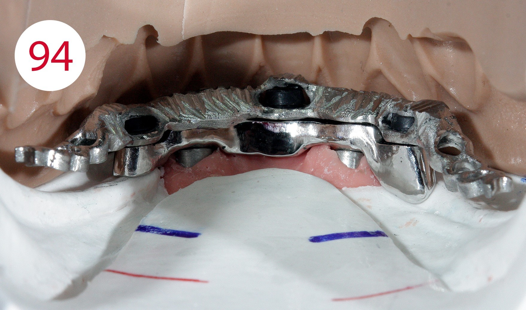
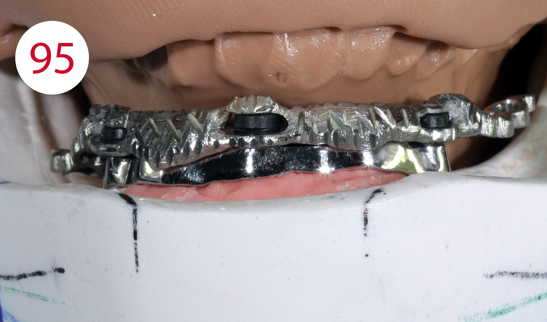
The profile was modeled in wax (Fig. 89). With the classical and traditional methods, we would have had to cast the bridge separately, adapt it, polish it and then build the superstructure on it, but with suitable measures it is possible to already construct the counterpart in this phase and implement it in metal. The application of a layer of Teflon tape created a cavity (Fig. 90) which served to prevent the counterpart from coming into contact with the bar due to the desired elasticity (Fig. 91, 92, 93).
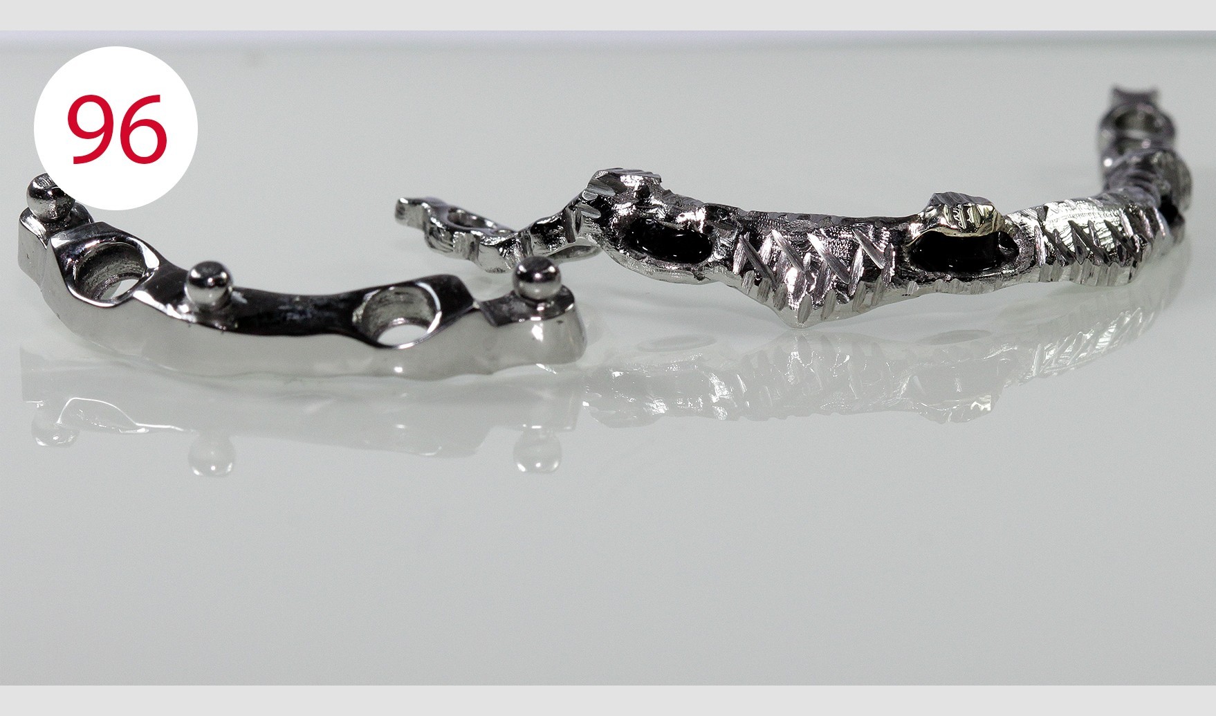
This phenomenon increases in a controlled manner after polishing the bar (Figs. 94, 95). Experience leads to the conviction that in many cases stability can be achieved through minimal adjustments at relatively low cost (Fig. 96).


Resin finishing and polymerization (DT Vittorio Capezzuto)
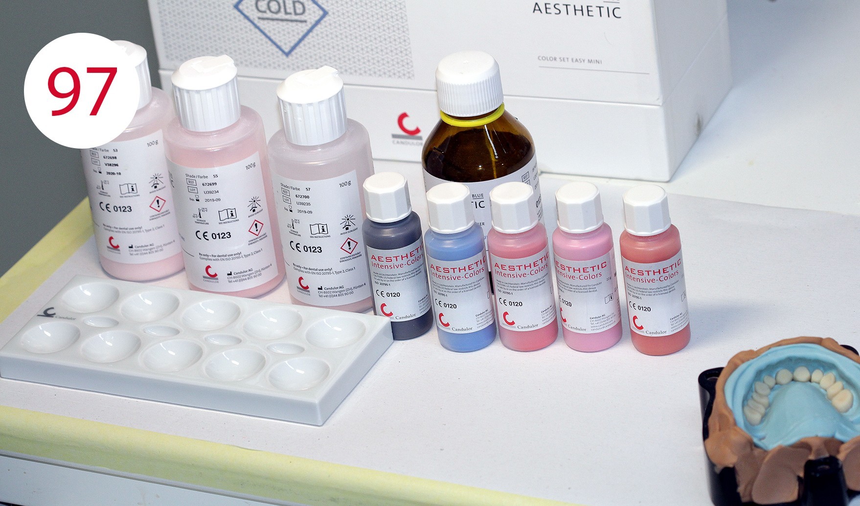
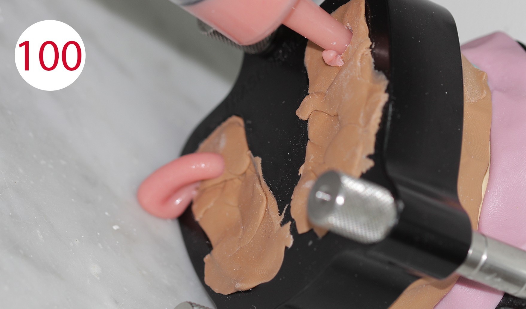
We used an injection system with ALU BIG (TRANSFORMER) investment ring for finishing the resin dentures. Beforehand, however, the dentures were characterized with AESTHETIC COLORS (CANDULOR) (Figs. 97, 98, 99). Intermediate polymerization was performed to sufficiently fix the first part of the PMMA and to better control shrinkage as well as any movements during the subsequent injection phase. The cold-curing AESTHETIC BLUE denture resin in COLOR 34 was injected with a syringe (Fig. 100) and cured for 30 min at 60 °C in a polymerization unit. During the curing phase, cold-curing polymers reach a temperature of more than 100 °C, so that the water at 60 °C is used for cooling during this time to avoid worrying about excessive shrinkage after curing.
Figs. 98 und 99: Characterization of the lip shield with AESTHETIC COLORS, with lighter PMMA color 53 adhering area of the mucosa, PMMA with darker red color 55 in the more vascularized area, with an accentuated coloring with AESTHETIC INTENSIVE COLORS; however, all characterization compounds must be premixed with the base PMMA in color 34
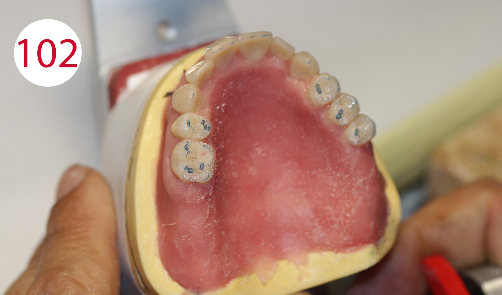
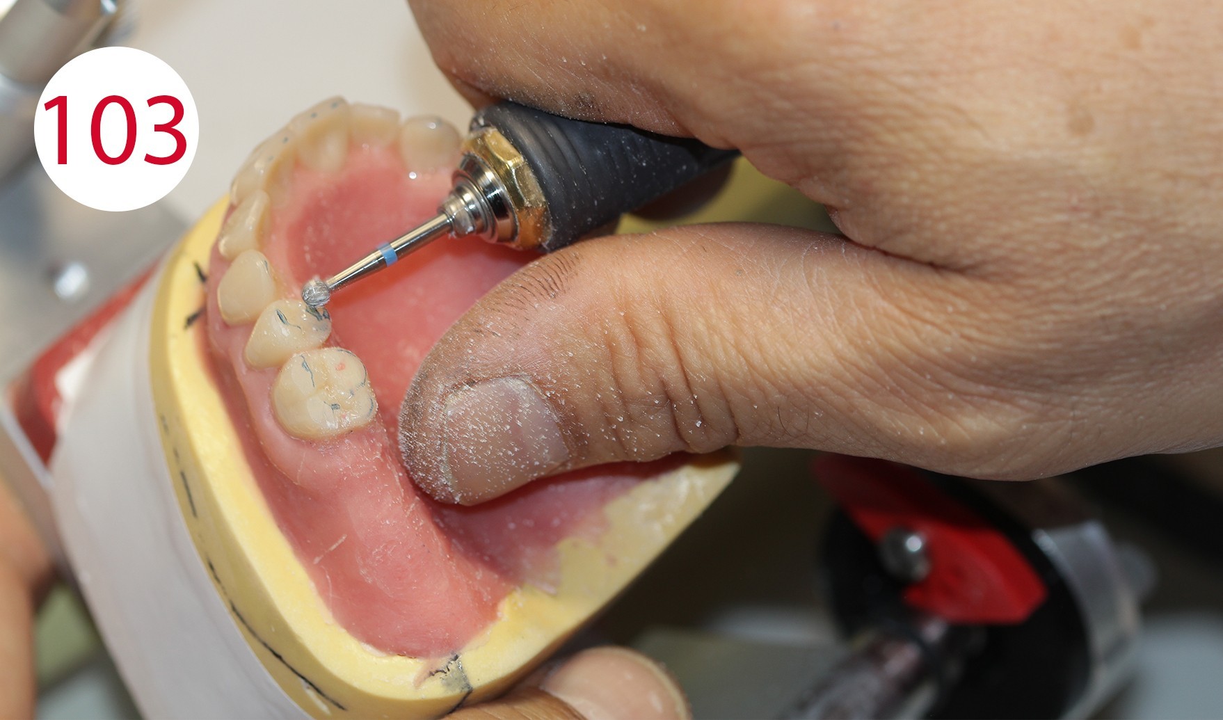
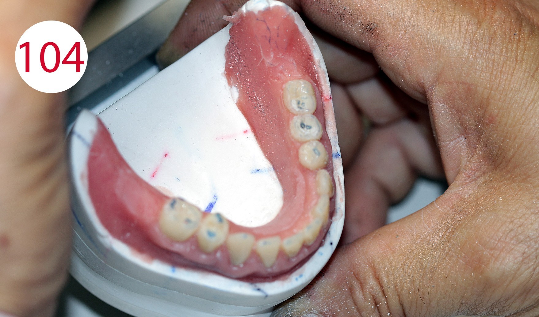
After devesting and before separation from the models, the dentures finished in resin (PMMA) are mounted in the articulator with the references with which the models were previously oriented, and the articulator was set, in order to check the occlusal contacts again during reocclusion (Figs. 101, 102). It was found that the vertical height had remained unchanged. Selective grinding is performed (Figs. 103, 104) to compensate for small deviations associated with insertion into the investment ring.
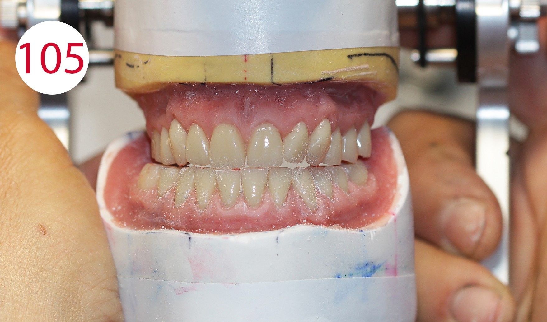
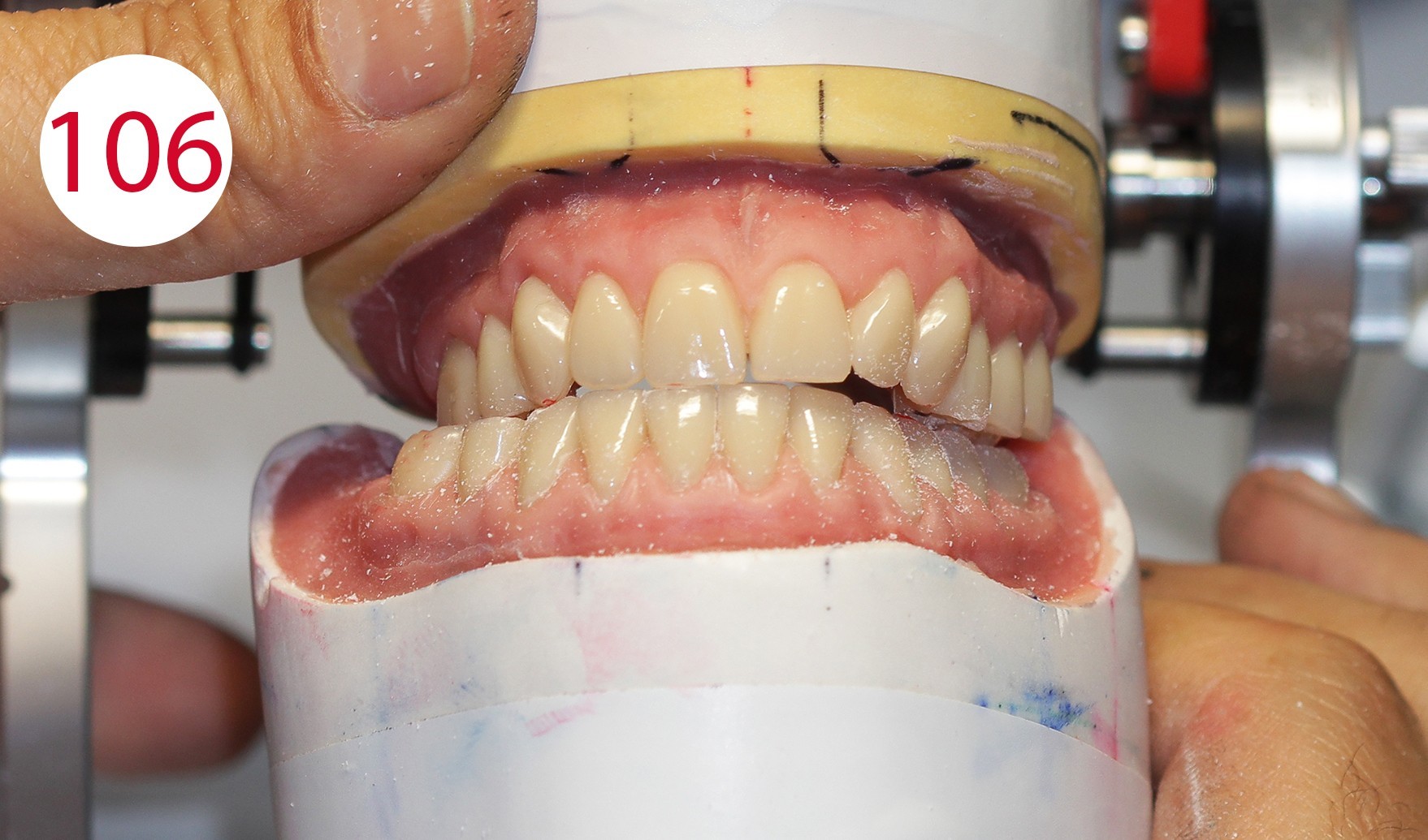
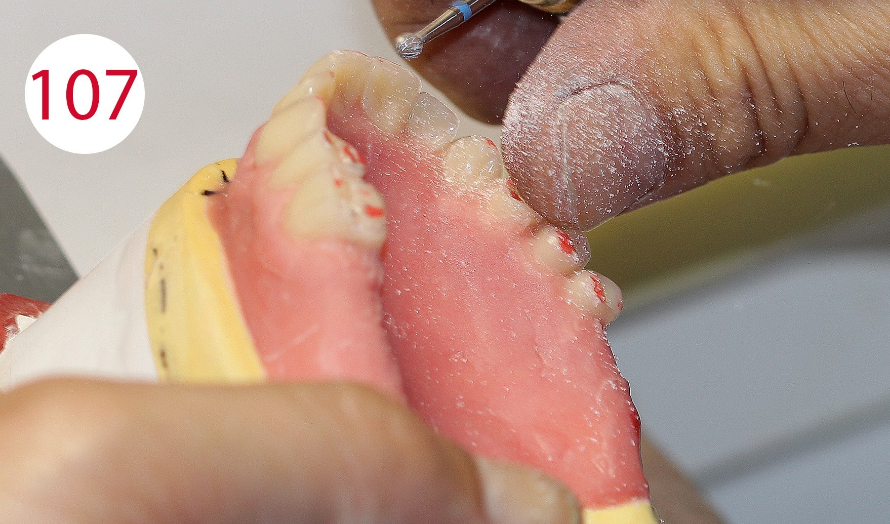
Even with injected PMMA, minimal displacement can occur. Therefore, the occlusal surfaces were equilibrated to obtain a wide and long centric, which is absolutely necessary for the antagonist contacts. Laterotrusion, protrusion (Figs. 105, 106, 107) and retrusion were checked; the latter can be simulated with the ARTIKULATOR CA 3.0 (CANDULOR) (Figs. 108, 109).
As soon as everything had been reoccluded within the functional clinical parameters, the dentures were separated from the models.


Final finishing and polishing of the dentures
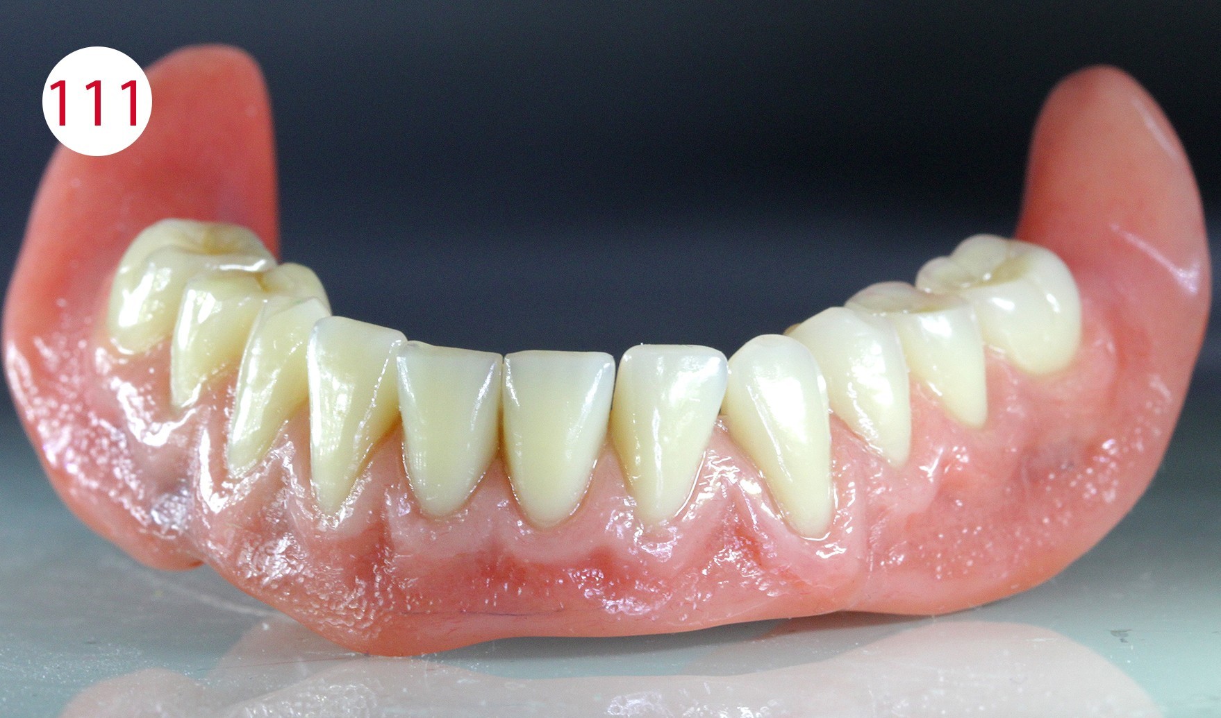
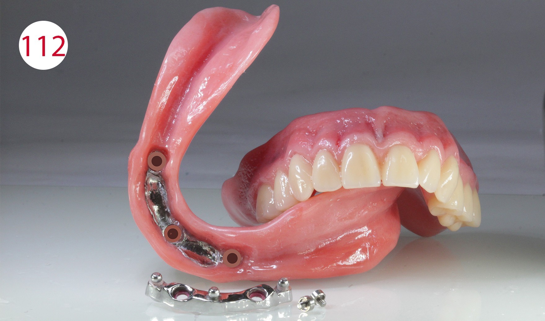
The previous check of the wall thickness and the applied color characterization on the basis of the detailed coloration schemes (CANDULOR) made it possible to achieve a high degree of predictability and reduced the need for technical corrections. The dentures were then stored in water for 12 hours, after which they were finished and polished with the handpiece. Polishing was performed with pumice stone and the polishing paste KMG (CANDULOR) recommended by the denture resin manufacturer (Figs. 110, 111, 112).
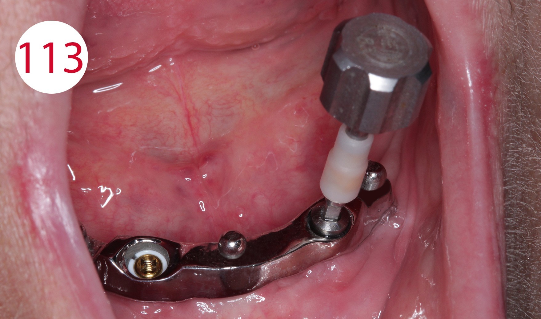
Incorporation of abutments, finishing
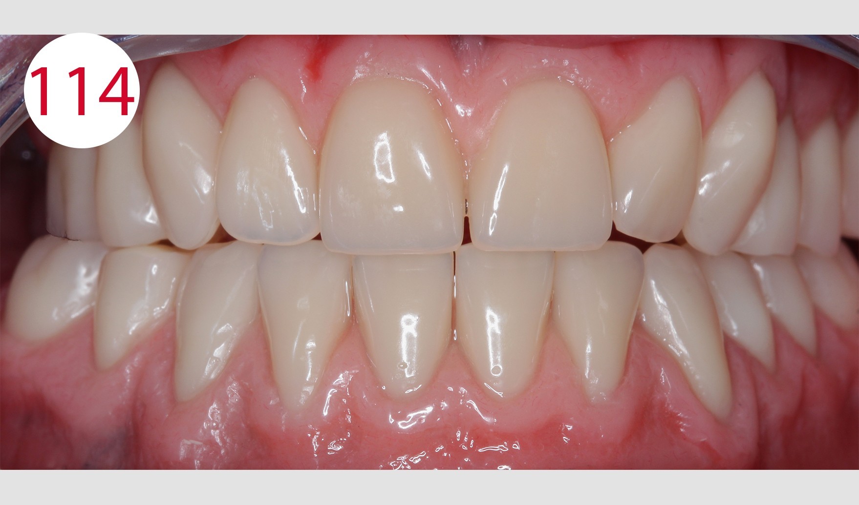
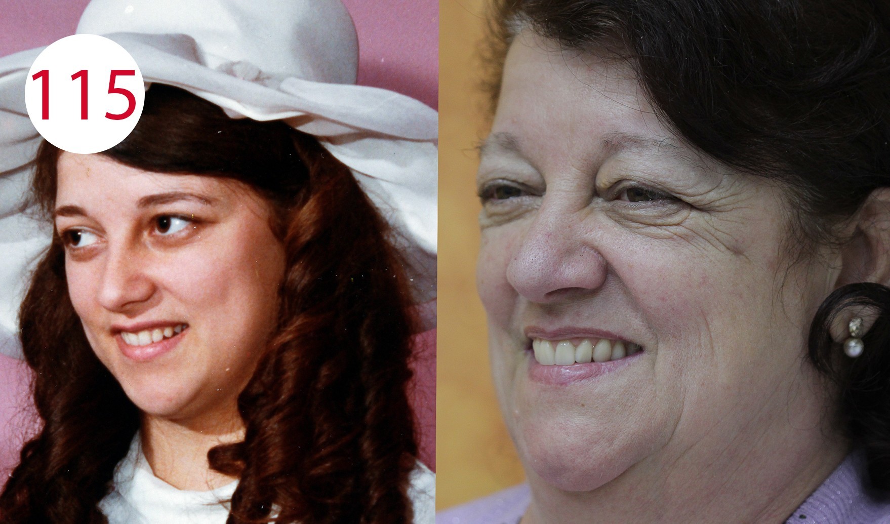
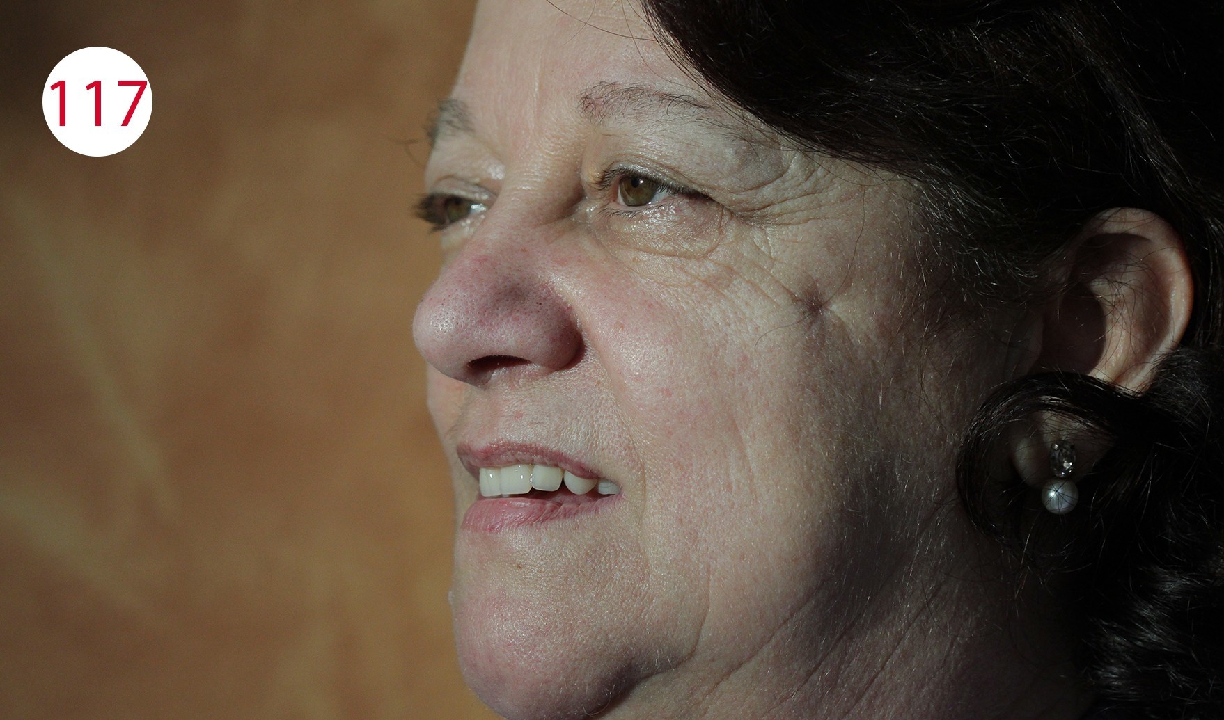
After completion of the dentures, the bar was connected to the Ot Equator abutments by positioning the final SEEGER (Fig. 113). This system is in fact designed to allow the fabrication of bars with passive connection to tertiary elements. The upper full denture and the lower overdenture were delivered to the dentist. There, the fit of the denture bases was checked in situ on the mucosa using COLTENE PSI and the occlusion was checked again using occlusion foils (Fig. 114). The patient was happy and satisfied with her new dentures and expressed this joy and sincere appreciation to the treatment team for having regained impeccable chewing function as well as her original appearance (Figs. 115, 116 and 117 left and right), which was very well received by the prosthetics team and regarded as an ideal reward.
Fig. 115: Left - Photo of the patient at the time of her wedding; Right - Comparison with her new (full denture) restoration
Figs. 116 and 117: The restoration in situ
Conclusion
The supply of insufficient and esthetically disadvantageous dentures made of partly "outdated" materials, the lack of regular check-ups as well as the increasing life expectancy are factors that lead us to deal with increasingly complex solutions on an ever larger scale. Planning, careful analysis, selection of suitable materials and close cooperation between dentist and dental technician are fundamental prerequisites for the realization of long-lasting removable mucosa-supported and also implant-supported removable restorations. In the case described here, the above factors were relevant. Our experience and the resulting conclusion is that the well-being of the patient comes first. This does not require searching for elaborate, complicated and sophisticated solutions at any price or solutions determined by current fashions. Even (relatively) simple solutions remain long-lasting, functional and esthetically pleasing if they are executed conscientiously.
Responsible dentist: Dr. Gennaro Galasso, Dental practice Chirurgodent, Cassino (FR)
Dental technical implementation: MDT Salvatore Chimenz, Dental laboratory, Scauri (LT)


Who is…?
After graduating from the vocational school for dental technicians in Cassino (province of Frosinone, Italy), he has been the owner of his own laboratory since 1994 and since then has mainly been involved with full dentures.
He gained his experience according to the philosophy of Prof. Gerber and attended numerous advanced training courses throughout Italy and in Switzerland (Zurich).
In 2015, he worked with the ANTLO Campania Association on the "Girovagantlo" project and qualified in second place in the first Trasformer competition with the "Full denture with Trasformer technique".
He is co-author of the book "Aspetti clinico-tecnici nella protesi combinata" (Clinical and technical aspects of combined dentures), teamwork media.
Since 2017 he has been working for Candulor as a specialist speaker throughout Italy, with training courses and workshops on the methodology of Prof. A. Gerber. In the same year he worked as an external tutor at the Institute of Dental Technicians Alfonso Casanova in Naples on the project "Donare un sorriso a chi soffre" ("Give a smile to the suffering") and achieved 5th place in the international competition "Create the best Candulor".
He currently works in his dental laboratory in Sparanise (province of Caserta, Italy).